Short description
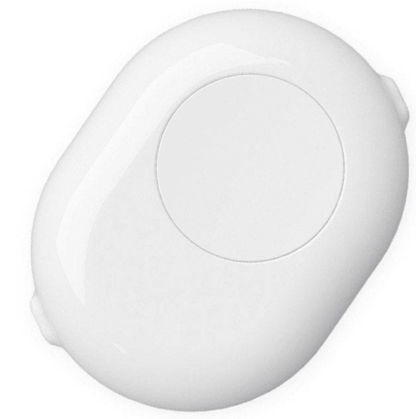
Shelly Button Add-on is an accessory that allows Shelly smart switches or dimmers to be used safely without inserting them into the wall box. It can be used with a wide range of plus and mini form-factor devices and easily turns every night light, fan or convector into a smart device.
Compatibility
- Gen1 devices: Shelly 1/1PM, Shelly 2.5 (switch mode), Shelly Dimmer 2
- Gen2 devices: Shelly Plus 1/1PM, Shelly Plus 2PM (switch mode), Shelly Plus 1/1PM Mini
- Gen3 devices: Shelly 1/1PM Gen3, Shelly 2PM Gen3 (switch mode), Shelly 1/1PM Mini Gen3, Shelly Dimmer Gen3 (when used with neutral)
- Gen4 devices (available so far): Shelly 1/1PM Gen4, Shelly 1/1PM Mini Gen4
Main features
- Retrofit: Turn every night-light, ambient light, fan or other appliance into a smart device
- Ease of access: Provide easy and safe access for children and people with disabilities to the home lights, fans or other devices
- Mounting: Fast and easy wiring by using the pre-installed cables
- Compatibility: Can be used with a wide range of plus and mini form-factor Shelly devices
Use cases
- Retrofitting: Turn your night lights into smart lights without the need of additional wiring — just insert a Shelly device of your choice and replace the existing switch with this elegant accessory.
- Comfort for children: Install it near your child’s bed and let the kid turn on and off the lights whenever they want. Dim down the lights remotely to provide a comfortable environment without entering the room.
- Ease of access: Use it as an additional wall switch for the lights to provide easy access for disabled people without the need of any construction works.
Main applications
- Residential
- MDU (Multi Dwelling Units – apartments, condominiums, hotels, etc.)
- Light commercial (small office buildings, small retail/restaurant/gas station, etc.)
- Government/municipal
- University/college
Device electrical interfaces
Inputs:
- 2 power supply inputs on push-in terminals: N (+) and L (Ʇ)
Outputs:
- 2 power supply outputs on push-in terminals: N (+) and L (Ʇ)
Interconnections:
- 5 cables: 1 L and 1 I (brown), 1 N (blue), 1 O (black), and 1 SW (white)
Supported load types
Load type should be compatible with the Shelly device that is going to be used with Shelly Button Add-on.
Specifications
| Quantity | Value |
|---|---|
| Physical | |
| Size (HxWxD): | 63 × 84 × 28 mm |
| Weight: | 45.62 g |
| Terminals: | Push-in |
| Power cable (size): | 3 mm |
| Conductor cross section: | 0.2 to 1.5 mm² / 24 to 16 AWG (solid, stranded, and bootlace ferrules) |
| Conductor stripped length: | 7 to 8 mm |
| Mounting: | Stand-alone/surface mounting |
| Shell material: | Plastic |
| Shell and print colors: | White shell, matte, gray print Black shell, matte, white print |
| Connectors color: | Black |
| Cables colors: | Brown, Blue, Black, White |
| Cables length: | 35 mm |
| Environmental | |
| Ambient working temperature: | -20°C to 40°C |
| Humidity: | 30% to 70% RH |
| Max. altitude: | 2000 m |
| Electrical | |
| Power supply: | 220–240 V~ 50 Hz |
| Output circuits ratings | |
| Max. switching voltage: | 240 V~ |
| Max. switching current: | 3 A and less than the rating of the Shelly device that is used |
Basic wiring diagrams
| Shelly 1 (Plus, Gen3, Gen4) inside Shelly Button Add-on | Shelly 1PM (Plus, Gen3, Gen4) inside Shelly Button Add-on | Shelly 2PM (Plus) inside Shelly Button Add-on | Shelly 2PM (Gen3, Gen4) inside Shelly Button Add-on | Shelly 1 Mini (Plus, Gen3, Gen4) inside Shelly Button Add-on | Shelly 1PM Mini (Plus, Gen3, Gen4) inside Shelly Button Add-on | Shelly Dimmer 2 inside Shelly Button Add-on | Shelly Dimmer Gen3 inside Shelly Button Add-on |
|---|---|---|---|---|---|---|---|
_wiring%20diagram.png) | _wiring%20diagram-20250613-151152.png) | _wiring%20diagram.png) | _wiring%20diagram-20250613-151102.png) | _wiring%20diagram-20250613-151023.png) | _wiring%20diagram.png) | 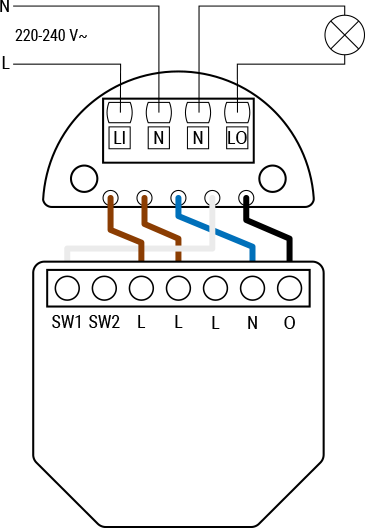 | 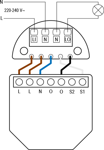 |
Legend
| Terminals | Description | Wires | Description |
|---|---|---|---|
| LI: | Live In (incoming live wire from power source) | N: | Neutral wire |
| N: | Neutral terminals (x2) | L: | Live wire (220–240 V~) |
| LO: | Live Out (switched live wire going to the output) | Brown: | Wire for live/input terminal |
| Device terminals | Blue: | Wire for neutral terminal | |
| L: | Live terminal (220–240 V~) | White: | Wire for switch terminal |
| N: | Neutral terminal | Black: | Wire for output terminal |
| O, O1, O2: | Load circuit output terminals | ||
| I: | Load circuit input terminal | ||
| S1, S2, SW, SW1, SW2: | Switch input terminals |
Troubleshooting
- Click here. This set of buttons will pop up.

- Select the pencil icon.
- Replace
instructionsin theExcerpt namedropdown with the corresponding device. - Select
Previewto make sure the correct content is selected. - Select
Save.
Compliance
- Click here. This set of buttons will pop up.
- Select the pencil icon.
- Replace
instructionsin theExcerpt namedropdown with the corresponding device. - Select
Previewto make sure the correct content is selected. - Select
Save.
Printed user guide
- Click here. This set of buttons will pop up.
- Select the pencil icon.
- Replace
instructionsin theExcerpt namedropdown with the corresponding device. - Select
Previewto make sure the correct content is selected. - Select
Save.