
Shelly Pro 4PM V2 is a modification of Shelly Pro 4PM V1 (SPSW-004PE16EU)
Differences with Shelly Pro 4PM V1 are marked by the ≠ symbol in the text below.
Main changes:
- Connectors: The four 2-terminal load connectors have been replaced by 5 individual screw terminals.
- LAN: Improved high voltage electrical distances.
Device identification (≠)
- Device name: Shelly Pro 4PM V2
- Device model: SPSW-104PE16EU
- Device SSID: ShellyPro4PM-XXXXXX
Short description
Shelly Pro 4PM is a DIN rail mountable four-channel smart switch with power measurement capabilities. Enhanced with all the gen2 firmware flexibility, LAN connectivity and color graphic display, it provides professional integrators with many more options for end customer solutions. It can work standalone in a local Wi-Fi network or it can also be operated through cloud home automation services.
Shelly Pro 4PM can be accessed, controlled and monitored remotely from any place where the user has internet connectivity, as long as the device is connected to a Wi-Fi router and the Internet.
Shelly Pro 4PM has an embedded Web Interface which can be used to monitor and control the device, as well as adjust its settings.
Main applications
- Residential
- MDU (Multi Dwelling Units - apartments, condominiums, hotels, etc.)
- Light commercial (small office buildings, small retail/restaurant/gas station, etc.)
- Government/municipal
- University/college
Integrations
- Alexa
- Samsung SmartThings
Simplified internal schematics (≠)
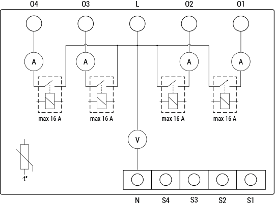
Device electrical interfaces
Inputs
- 4 switch/button inputs on screw terminals: S1, S2, S3, and S4
- 2 power supply inputs on screw terminals: 1 N and 1 L
Outputs
- 4 relay outputs: O1, O2, O3, and O4
Ethernet port
- 1 RJ45 connector
⚠ CAUTION! Plug in or unplug the LAN cable only when the device is powered off! The LAN cable connector must not be metallic in the parts touched by the user to plug in or unplug the cable.
Connectivity
- Ethernet
- Wi-Fi
- Bluetooth
Safety features
- Overheating protection
- Overvoltage protection
- Overcurrent protection
- Overpower protection
Supported load types
- Resistive (incandescent bulbs, heating devices)
- Capacitive (capacitor banks, electronic equipment, motor start capacitors)
- Inductive with RC Snubber (LED light drivers, transformers, fans, refrigerators, air-conditioners)
User interface
Inputs
Three press buttons on the front plate:
Left button:
- Press to scroll up in the currently displayed menu
Middle button:
- Press to scroll down in the currently displayed menu
Right button:
- Press to wake up the device display
- Press and hold to get into the menu screen
- Press to select a menu item
- Press and hold while in a sub-menu to move to the main menu
Outputs
Color LCD.
The LCD top bar displays short status information:
- Time
- Bluetooth connection status:
- Disabled – no icon
- Enabled – blue icon
- LAN status:
- Disabled – no icon
- Enabled, but not connected – red icon
- Connected – green icon
- Wi-Fi STA status:
- Disabled – no icon
- Enabled, but not connected – red icon
- Connected – green icon
- Wi-Fi AP status:
- Disabled – no icon
- Enabled, but not connected – red icon
- Connected – green icon
- Cloud status:
- Disabled – no icon
- Enabled, but not connected – red icon
- Connected – green icon
The rest of the LCD is used to display the device menu screens:
- Main (default) screen:
- Output 1 on/off
- Output 2 on/off
- Output 3 on/off
- Output 4 on/off
- Network:
- Wi-Fi AP enable/disable
- Wi-Fi enable/disable
- Ethernet enable/disable
- Bluetooth enable/disable
- Status:
- Displays complete status information
- Maintenance:
- Wi-Fi reset
- Factory reset
- Reboot
Specifications
| Type | Value |
|---|---|
| Physical | |
| Size (HxWxD): | 96×53×59 ±0.02 mm / 3.78×2.01×2.32 ±0.02 in |
| Weight | |
| Mounting | DIN rail |
| Screw terminals max torque | 0.4 Nm / 3.5 lbin (green connectors) |
| Conductor cross section | 0.5 to 2.5 mm² / 20 to 14 AWG (green connectors) |
| Conductor stripped length | 6 to 7 mm / 0.24 to 0.28 in (green connectors) |
| Shell material | Plastic |
| Color | Black |
| Environmental | |
| Ambient temperature | -20 °C to 40 °C / -5 °F to 105 °F |
| Humidity | 30 % to 70 % RH |
| Max. altitude | 2000 m / 6562 ft |
| Electrical | |
| Power supply voltage AC | 110 - 240 V |
| Power supply voltage DC | N/A |
| Power consumption | < 4 W |
| Neutral not needed | No |
| Output circuits ratings | |
| Max switching voltage AC | 240 V |
| Max switching voltage DC | N/A |
| Max switching current AC | 16 A per channel, 40 A total |
| Max switching current DC | N/A |
| Sensors, meters | |
| Voltmeter (AC) | Yes |
| Ammeter (AC) | Yes |
| Internal-temperature sensor | Yes |
| Radio | |
| RF band | 2400 - 2495 MHz |
| Max. RF power | <20 dBm |
| Wi-Fi protocol | 802.11 b/g/n |
| Wi-Fi Range | Up to 30 m / 100 ft indoors and 50 m / 160 ft outdoors (Depends on local conditions) |
| Bluetooth Protocol | 4.2 |
| Bluetooth Range | Up to 10 m / 33 ft indoors and 30 m / 100 ft outdoors (Depends on local conditions) |
| MCU | |
| CPU | ESP32-D0WDQ6 |
| Flash | 8 MB |
| Firmware capabilities | |
| Schedules | 20 |
| Webhooks (URL actions) | 20 with 5 URLs per hook |
| Scripting | Yes |
| MQTT | Yes |
| CoAP | No |
Basic wiring diagram (≠)
| Resistive load | Inductive load and RC snubber |
|---|---|
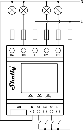 | 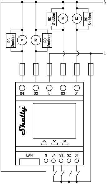 |
Legend
| Terminals | Description | Wires | Description |
|---|---|---|---|
| O1, O2, O3, O4 | Load circuit output terminals | L | Live (110–240 V) wire |
| S1, S2, S3, S4 | Switch/button input terminals | N | Neutral wire |
| L | Live (110–240 V) terminals | ||
| N | Neutral terminal | ||
| LAN | Local Area Network RJ45 connector |
Shelly Smart Control
Shelly Web user interface
Troubleshooting
...
Components and APIs
Printed user guide
- Shelly Pro 4PM V2 multilingual printed user and safety guide
- Ръководство за употреба и безопасност (Bulgarian)
Compliance
- Shelly Pro 4PM multilingual EU declaration of conformity 2025-07-21
- Shelly Pro 4PM UK PSTI ACT Statement of compliance
- Shelly Pro 4PM AU NZ Certificate for Suitability
Compliance archive
Shelly Pro 4PM multilingual EU declaration of conformity 1-2 2022-11-22
Installation guides
(No installation guides listed at this time)