Device Identification
Error rendering macro 'excerpt-include': User '712020:515aa595-e304-41f3-886a-d9b6b0b7f5a3' does not have permission to view the page 'DEV:Wave Devices Images'.
Terminology
Error rendering macro 'excerpt-include': User '712020:515aa595-e304-41f3-886a-d9b6b0b7f5a3' does not have permission to view the page 'DEV:Terminology Wave'.
Short Description
Error rendering macro 'excerpt-include': User '712020:515aa595-e304-41f3-886a-d9b6b0b7f5a3' does not have permission to view the page 'DEV:About the Device'.
Controls position of blinds, rollers, shades, venetian blinds, etc.
click here to see how to control the shutter
Unable to render {include}: The included page could not be found.
Main Applications
Error rendering macro 'excerpt-include': User '712020:515aa595-e304-41f3-886a-d9b6b0b7f5a3' does not have permission to view the page 'DEV:Main applications'.
Integrations
Error rendering macro 'excerpt-include': User '712020:515aa595-e304-41f3-886a-d9b6b0b7f5a3' does not have permission to view the page 'DEV:Integrations'.
Simplified Internal Schematics
Error rendering macro 'excerpt-include': User '712020:515aa595-e304-41f3-886a-d9b6b0b7f5a3' does not have permission to view the page 'DEV:Simplified internal schematics'.
Device Electrical Interfaces
Inputs
Error rendering macro 'excerpt-include': User '712020:515aa595-e304-41f3-886a-d9b6b0b7f5a3' does not have permission to view the page 'DEV:Device electrical interfaces'.
Error rendering macro 'excerpt-include': User '712020:515aa595-e304-41f3-886a-d9b6b0b7f5a3' does not have permission to view the page 'DEV:Device electrical interfaces'.
Outputs
Error rendering macro 'excerpt-include': User '712020:515aa595-e304-41f3-886a-d9b6b0b7f5a3' does not have permission to view the page 'DEV:Device electrical interfaces'.
Connectivity
Error rendering macro 'excerpt-include': User '712020:515aa595-e304-41f3-886a-d9b6b0b7f5a3' does not have permission to view the page 'DEV:Basic Functions'.
Safety Features
Click to unhide/hide
Unable to render {include}: The included page could not be found.
Supported Load Types
- Inductive with RC Snubber (120 V AC electric motors)
User Interface
Unable to render {include}: The included page could not be found.
LED Signalisation
Click to see LED signalisation
General Rules
- To switch between Normal and Setting modes, press the S button once.
- Solid LED means that the Device is in Setting mode (this does not apply to plugs). When the Device is in Setting mode, it automatically switches to Normal mode after 10s.
- If the LED is not in Alarm mode, it will turn off after a timeout of 30 min (this does not apply to plugs). Press on the S button or Device power cycle wakes the LED up for 30 min.
Normal mode LED status: Normal mode is defined by a stable Device function that can last infinitely long.
LED type: RGB dimmable
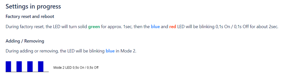
Normal Mode
Removed (excluded)/not calibrated
The LED will be blinking blue in Mode 1 for 30 min after every power cycle and 10 min after S button pressed.

Removed (excluded)/calibrated
The LED will be blinking blue and yellow in Mode 1 for 30 min after every power cycle and 10 min after S button pressed.

Added (included)/not calibrated
The LED will be blinking green in Mode 1 for 30 min after every power cycle and 10 min after S button pressed.

Added (included)/calibrated
The LED will be blinking green and yellow in Mode 1 for 30 min after every power cycle and 10 min after S button pressed.

Technical Specifications
Error rendering macro 'excerpt-include': User '712020:515aa595-e304-41f3-886a-d9b6b0b7f5a3' does not have permission to view the page 'DEV:Technical Specifications'.
Basic Wiring Diagram
| > Error rendering macro 'excerpt-include': User '712020:515aa595-e304-41f3-886a-d9b6b0b7f5a3' does not have permission to view the page 'DEV:Wiring diagrams'. | > Error rendering macro 'excerpt-include': User '712020:515aa595-e304-41f3-886a-d9b6b0b7f5a3' does not have permission to view the page 'DEV:Wiring diagrams'. | > Error rendering macro 'excerpt-include': User '712020:515aa595-e304-41f3-886a-d9b6b0b7f5a3' does not have permission to view the page 'DEV:Wiring diagrams'. |
| > Error rendering macro 'excerpt-include': User '712020:515aa595-e304-41f3-886a-d9b6b0b7f5a3' does not have permission to view the page 'DEV:Wiring diagrams'. | > Error rendering macro 'excerpt-include': User '712020:515aa595-e304-41f3-886a-d9b6b0b7f5a3' does not have permission to view the page 'DEV:Wiring diagrams'. |
Legend
Unable to render {include}: The included page could not be found.
Disclaimers and Warnings
Error rendering macro 'excerpt-include': User '712020:515aa595-e304-41f3-886a-d9b6b0b7f5a3' does not have permission to view the page 'DEV:Disclaimers and Warnings'.
Unable to render {include}: The included page could not be found.
About Z-Wave®
Error rendering macro 'excerpt-include': User '712020:515aa595-e304-41f3-886a-d9b6b0b7f5a3' does not have permission to view the page 'DEV:About Z-Wave®'.
Adding and Removing the Device to a Z-Wave® Network
Click to see how to add, remove and reset the Device
Unable to render {include}: The included page could not be found.
Z-Wave® Security and Device Specific Key (DSK)
Click to see about the Security and the DSK
Error rendering macro 'excerpt-include': User '712020:515aa595-e304-41f3-886a-d9b6b0b7f5a3' does not have permission to view the page 'DEV:Z-Wave® Security 2 and Device Specific Key (DSK)'.
Setting Parameters
Click here to see the Z-Wave Parameters
Parameter No. 1 – Push-button (momentary) / bistable (toggle switch) selection
With this parameter, you can select between the switch type: push-button (momentary) or on/off toggle switch connected to SW1 and SW2 inputs.
- Value size: 1 Byte
- Default value: 0
- Values & descriptions:
- 0 - momentary switch
- 1 - toggle switch (contact closed - ON / contact opened - OFF)
- 2 - single, momentary switch (the switch should be connected to SW1 terminal)
NOTE: When set = 2, 1x click on SW1 up - 1x click on SW1 stop - 1x click down
Parameter No. 3 – Inputs orientation
This parameter allows to reverse the operation of switches connected to SW1 and SW2 inputs without changing the wiring.
- Value size: 1 Byte
- Default value: 0
- Values & descriptions:
- 0 - default (SW1 - O1, I2 - O2)
- 1 - reversed (SW1 - O2, I2 - O1)
Parameter No. 5 – Output orientation
This parameter allows to reverse the operation of O1 and O2 without changing the wiring (in case of invalid motor connection) to ensure proper operation.
- Value size: 1 Byte
- Default value: 0
- Values & descriptions:
- 0 - default (O1 - UP, O2 - DOWN)
- 1 - reversed (O1 - DOWN, O2 - UP)
Parameter No. 40 – Power Consumption Reporting
Choose by how much the power (W) consumption needs to increase or decrease to be reported. Values correspond to percentages, so if 50 is set (by default), the Device will report any power consumption changes of 50 % or more, compared to the last reading.
- Values size: 1 Byte
- Default value: 50
- Values & descriptions:
- 0 - Power consumption reporting disabled
- 1 - 100 = 1 % - 100 % Power consumption reporting enabled. New value is reported only when the power consumption in real time changes by more than the percentage value set in this parameter, compared to the previous power consumption reading, starting at 1 % (the lowest value possible).
NOTE: Power consumption needs to increase or decrease by at least 1 Watt to be reported, REGARDLESS of the percentage set in this parameter.
Parameter No. 71 – Operating modes
Choose between the two operating modes. In shutter mode, you can select up/down/stop. In venetian mode, an additional widget/endpoint is displayed in the UI interface, which you can use to control the tilt position of the slats.
- Values size: 1 Byte
- Default value: 0
- Values & descriptions:
- 0 - Shutter mode
- 1 - Venetian mode with (up/down and slats rotation)
- 2 – Manual time set (No end switches)
NOTE: If the motor is not equipped with end switches set value to 2 and set the traveling time (Parameter No. 74 & 75).
Parameter No. 72 – Venetian blind slats turning time
Set the time required for the slats to make a full turn (180 degrees).
NOTE: Make sure that working mode is set to venetian (Par. No. 71 =1)
- Values size: 2 Byte
- Default value: 150 = 1.5 seconds
- Values & descriptions:
- 0 - turning time disabled
- 1 - 32767 = 0.01 seconds – 327.67 seconds
NOTE: If the set time is too long and a full turn was already performed, the device will start moving up or down for the remaining time. In this case, shorten the turning time.
Parameter No. 73 – Slats position after moving
This parameter is used to enable/disable the slats to return to the previously set position, after being activated via the gateway, push-button operation or when the lower limit switch is reached.
- Values size: 1 Byte
- Default value: 1
- Values & their descriptions:
- 0 - disable
- 1 – enable
NOTE: Make sure that working mode is set to venetian (Par. No. 71=1)
Parameter No. 76 – Motor operation detection
Define the power consumption threshold at the end positions. Based on this value, the Device will know that the shutters reached the limit switches.
- Values size: 1 Byte
- Default value: 1
- Values & their descriptions:
- 0 - Disabled: reaching a limit switch will not be detected
- 1 - Auto power calibration
- 2 - 255 (2-255W) - report interval
NOTE: For correct auto power calibration the shutter calibration must be performed!
Parameter No. 78 – Forced shutter calibration
By setting this parameter to value 1 the Device will start executing force calibration procedure. The parameter also reports the calibration status by sending the get parameter value command.
NOTE: Check chapter Functionality with calibration details
NOTE: During the calibration procedure the blind moves up, down, up, and down to 50%.
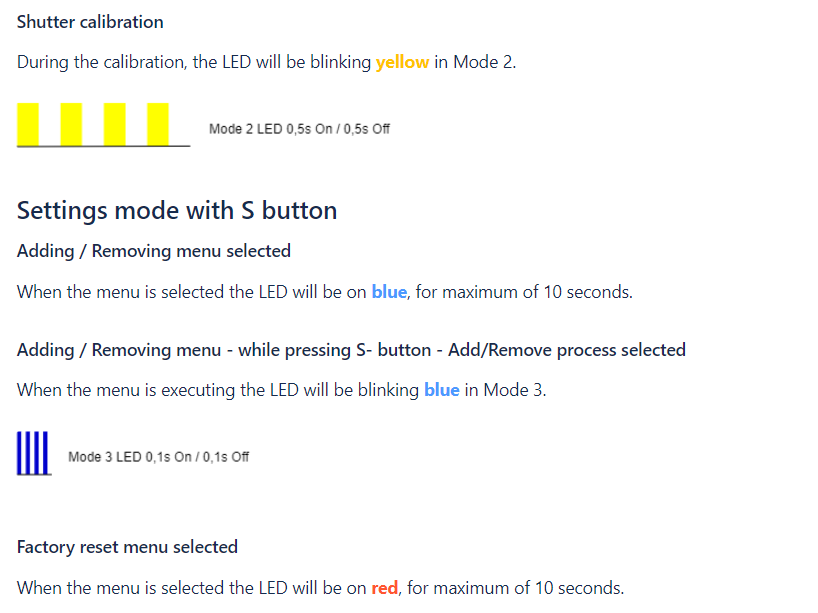
NOTE: During the calibration procedure the yellow LED is blinking.
- Values size: 1 Byte
- Default value: 3 (after factory reset)
- Values & their descriptions:
- 1 - start calibration
- 2 - device is calibrated (read only)
- 3 - device is not calibrated (read only)
- 4 - calibration error (read only)
Parameter No. 80 – Motor stop delay after limit switch detection
This parameter defines the delay time for the motor to turn off, after reaching the limit switch.
- Values size: 1 Byte
- Default value: 10
- Values & their descriptions:
- Default value 10 = (1s)
- 0-127 (0-12.7s) - time
Parameter No. 85 – Power consumption max delay time
Define the maximum time before the power consumption of the motor is read from the Device, after one of the relays is switched on. If there is no power consumption during the set time (motor is not connected, damaged or requires longer time to start, motor is at the end position), the relay will switch off. This time is defined by entering it manually.
- Values size: 1 Byte
- Default value: 30
- Values & descriptions:
- 0 = time is set automatically
- 3 - 50 = 0.3seconds – 5seconds (100ms resolution)
Parameter No. 91 – Max. Motor moving time
When the shutter is not calibrated (or the motor is not equipped with a limit switch), this parameter defines the movement time of the motor.
- Values size: 2 Byte
- Default value: 120
- Values & descriptions:
- value = 1 - 32000s
Command Classes
Click to see the Z-Wave Command Classes
Z-Wave Supported Command Classes:
- COMMAND_CLASS_ZWAVEPLUS_INFO_V2
- COMMAND_CLASS_SWITCH_MULTILEVEL_V4
- COMMAND_CLASS_ASSOCIATION_3
- COMMAND_CLASS_MULTI_CHANNEL_ASSOCIATION_V4
- COMMAND_CLASS_ASSOCIATION_GRP_INFO_V3
- COMMAND_CLASS_NOTIFICATION_V9
- COMMAND_CLASS_TRANSPORT_SERVICE_V2
- COMMAND_CLASS_VERSION_V3
- COMMAND_CLASS_MANUFACTURER_SPECIFIC_V2
- COMMAND_CLASS_DEVICE_RESET_LOCALLY_V1
- COMMAND_CLASS_INDICATOR_V4
- COMMAND_CLASS_POWERLEVEL_V1
- COMMAND_CLASS_SECURITY_V1
- COMMAND_CLASS_SECURITY_2_V1
- COMMAND_CLASS_MULTI_CHANNEL_V4
- COMMAND_CLASS_SUPERVISION_V2
- COMMAND_CLASS_FIRMWARE_UPDATE_MD_V7
- COMMAND_CLASS_CONFIGURATION_V4
- COMMAND_CLASS_SWITCH_BINARY_V2
- COMMAND_CLASS_APPLICATION_STATUS_V2
- COMMAND_CLASS_METER_V6
Endpoint 1:
- Device Class: BASIC_TYPE_ROUTING_SLAVE, GENERIC_TYPE_SWITCH_MULTILEVEL, SPECIFIC_TYPE_CLASS_B_MOTOR_CONTROL
- Command Classes:
COMMAND_CLASS_ZWAVEPLUS_INFO_V2,
COMMAND_CLASS_SWITCH_MULTILEVEL_V4,
COMMAND_CLASS_ASSOCIATION_V3,
COMMAND_CLASS_ASSOCIATION_GRP_INFO_V3,
COMMAND_CLASS_MULTI_CHANNEL_ASSOCIATION_V4,
COMMAND_CLASS_NOTIFICATION_V9,
COMMAND_CLASS_SUPERVISION_V2,
COMMAND_CLASS_SECURITY_V1,
COMMAND_CLASS_SECURITY_2_V1,
COMMAND_CLASS_SWITCH_BINARY_V2,
COMMAND_CLASS_APPLICATION_STATUS_V1,
COMMAND_CLASS_METER_V6
Endpoint 2:
- Device Class: BASIC_TYPE_ROUTING_SLAVE, GENERIC_TYPE_SWITCH_MULTILEVEL, SPECIFIC_TYPE_CLASS_B_MOTOR_CONTROL
- Command Classes:
COMMAND_CLASS_ZWAVEPLUS_INFO_V2,
COMMAND_CLASS_SWITCH_MULTILEVEL_V4,
COMMAND_CLASS_ASSOCIATION_V3,
COMMAND_CLASS_ASSOCIATION_GRP_INFO_V3,
COMMAND_CLASS_MULTI_CHANNEL_ASSOCIATION_V4,
COMMAND_CLASS_NOTIFICATION_V9,
COMMAND_CLASS_SUPERVISION_V2,
COMMAND_CLASS_SECURITY_V1,
COMMAND_CLASS_SECURITY_2_V1,
COMMAND_CLASS_SWITCH_BINARY_V2,
COMMAND_CLASS_APPLICATION_STATUS_V1,
COMMAND_CLASS_METER_V6
Endpoint 2 is supported by the module only when the Parameter No. 71 is set to the value 1.
COMMAND_CLASS_BASIC SET AND MULTILEVEL SWITCH SET
- Set to 0x00 → Go to 0%
- Set to 0x01..0x62 → Go to specific target value
- Set to 0xFF → Go to 100%
MULTILEVEL SWITCH LEVEL CHANGE
- Start Down → Go to 0%
- Start Up → Go to 100%
- Stop → Stop
BASIC REPORT AND MULTILEVEL SWITCH REPORT
- At 0%: 0x00
- Unknown position: 0xFE
- Known position: 0x01..0x62 (The position is approximated!)
- At 100%: 0x63
BINARY SWITCH SET
- Moving to 0% → Binary Switch Set=0x00 → Go to 0%
- Moving to 100% → Binary Switch Set=0x00 → STOP
- Moving to 0% → Binary Switch Set=0x01..0X63,0xFF → STOP
- Moving to 100% → Binary Switch Set=0x01..0X63,0xFF → Go to 100%
COMMAND_CLASS_METER
- Default values:
- Rate Type = 1 (Import)
- Scale = 0 (kWh)
- Energy consumption (kWh) is reported with the step increase of 0.1.
- This product can be operated in any Z-Wave network with other Z-Wave certified devices from other manufacturers. All mains operated nodes within the network will act as repeaters regardless of vendor to increase reliability of the network.
Notifications Command Class
Click to see the Z-Wave Notification Command Class
Wave Shutter supports the following notifications:
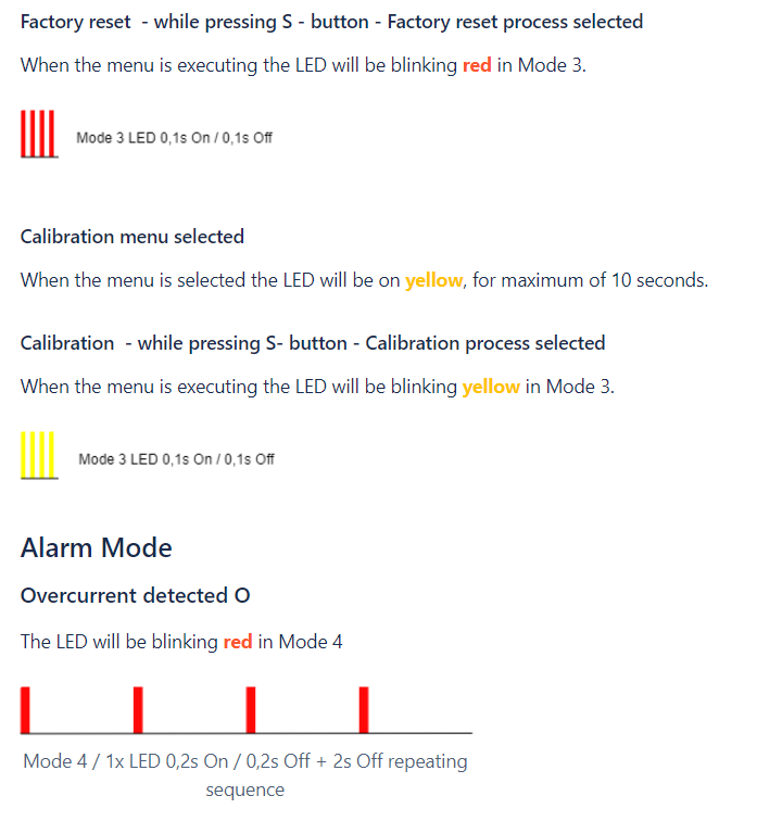
- In case of exceeding the power of >1100 W for more than 5 seconds, Shutter automatically turns off the output and the overload notification is sent.
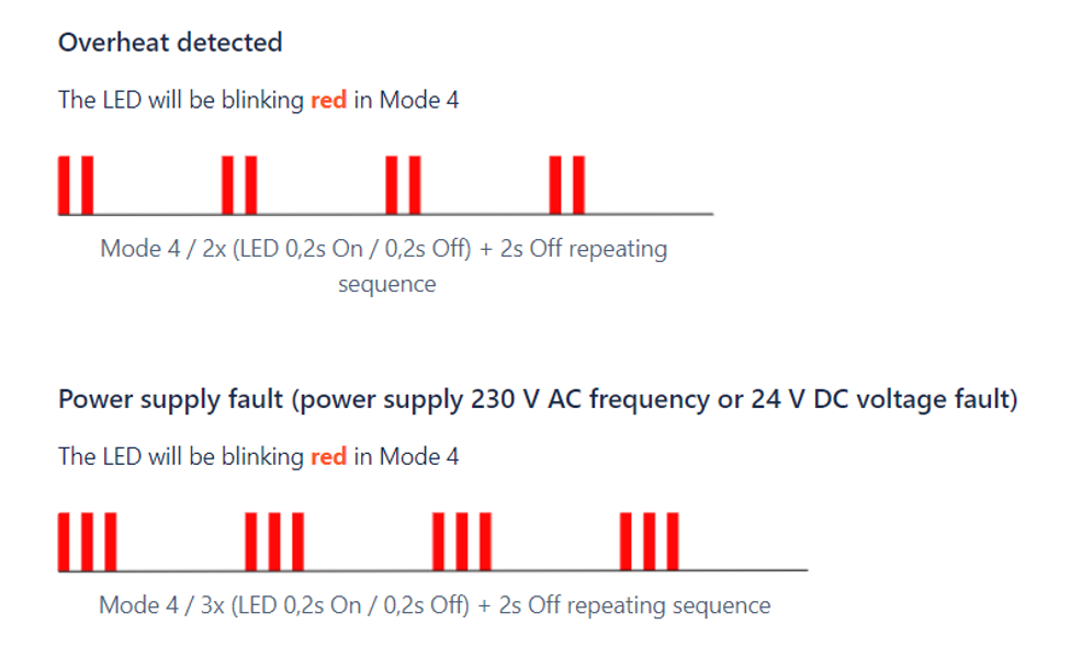
- In case the exceeding the inside device temperature for more than 5s Shutter automatically turns off the output and the overtemperature notification is sent.
| Notification Type | Notification Event |
|---|---|
| Power Management (0x08) | Over-load detected (0x08) |
| Heat alarm (0x04) | Overheat detected (0x02) |
Associations
Click to see the Z-Wave Associations
Associations are used for direct communication between the Device and other devices within your Z-Wave network without the need of the Z-Wave gateway.
- Max. number of associated devices per group is 9. This value is fixed and cannot be configured.
- Each association group supports the association of up to 9 devices (nodes).
- To avoid network delays, we recommend limiting the number of associated devices to no more than 5 per group.
- “Lifeline Group” is reserved solely for a gateway and hence only 1 node can be assigned.
| Group | Name | Allowed nodes | Description |
|---|---|---|---|
| 1 | Lifeline | 1 | Reserved for communication with the primary gateway (hub), 1 node allowed. Supports the following command classes:
|
| 2 | Roller Shutter | 9 | Switch multilevel for shutter position Click - start level change - Click - stop level change… Triggered by SW1 or SW2 |
| 3 | Venetian | 9 | Switch multilevel for slats position Hold - start level change - release - stop level change Triggered by SW1 or SW2 |
| 4 | on/off during movement O1,O2 | Group 4: Basic on/off (Triggered at sensing moving direction of roller: up= FF, down = 00) up to 16 nodes. When blinds are moving up, Shutter will send Basic set ON command to associated device and associated device will turn ON. When blinds are moving down, Flush Shutter will send Basic set OFF command to associated device and the device will turn OFF | |
| 5 | on top = OFF on bottom = ON | Group 5: Basic on/off (Triggered at reaching roller position: bottom=FF, top=0) up to 16 nodes. When blinds reach upper position, Shutter will send Basic set OFF command to associated device and the device will turn OFF. When blinds reach down position Flush Shutter will send Basic set ON command to associated device and the device will turn ON. |
Description:
- Turn ON = Shutter move UP = move to 100%
- Turn OFF = Shutter move DOWN = move to 0%
Association mapping:
| Root device | Associated Groups | Note |
|---|---|---|
| 1,2,3,4,5,6,7 | Groups 6 & 7 are mapped groups 2 & 3 of E2 Groups 1 to 5 are mapped groups 1 to 5 of E1 |
| Endpoint 1 (E1) | 1,2,3,4,5 | | | Endpoint 2 (E2) | 1,2,3 | |
Multilevel commands send to association groups (Shutter mode par.71=0):
| Parameter 1 (switch type) | Inputs | Quick press | Hold | Release |
|---|---|---|---|---|
| 0 - push button | SW1 or SW2 | Group2: start/stop level change Device sends the switch multilevel start level change UP or DOWN | Group3: start level change Device sends the switch multilevel start level change UP or DOWN | Group3: stop level change Device sends Switch multilevel stop level change |
| 1 - switch | SW1 or SW2 | Group2: start/stop level change | NA | NA |
| 2 - single push button (SW1) | SW1 | Group2: start/stop level change | Group3: start level change | Group3: stop level change |
Multilevel commands send to association groups (Venetian mode par.71=1):
| Parameter 1 (switch type) | Inputs | Quick press | Hold | Release |
|---|---|---|---|---|
| 0 - push button | SW1 or SW2 | Group2: start/stop level change Device sends the switch multilevel start level change UP or DOWN | NA Device does not send any association | Group3: set level Only after the pushbutton is released, the device sends out switch multilevel set 0…99%) |
| 1 - switch | SW1 or SW2 | Group2: start/stop level change | NA | NA |
| 2 - single push button (SW1) | SW1 | Group2: start/stop level change | NA Device does not send any association | Group3: Only after the pushbutton is released, the device sends out switch multilevel set 0…99%) |
Z-Wave® Important Disclaimer
Error rendering macro 'excerpt-include': User '712020:515aa595-e304-41f3-886a-d9b6b0b7f5a3' does not have permission to view the page 'DEV:Disclaimers and Warnings'.
Troubleshooting
For troubleshooting please visit our support portal: Support
Compatibility
Error rendering macro 'excerpt-include': User '712020:515aa595-e304-41f3-886a-d9b6b0b7f5a3' does not have permission to view the page 'DEV:Compatibility reports'.
Functionality Test Table
| Function | Meaning / tested |
|---|---|
| On/Off | if device respond to the app UI On/Off command |
| SW On/Off | if device reports On/Off changes by SW input |
| Dimming | if device respond to app UI dimming command |
| SW Dimming | if device report dimming state change by SW input |
| Watts | if Watts are reported (unsolicited) |
| kWh | if kWh are reported (unsolicited) |
| Up/Down | if device respond to the app UI Up/Down command |
| SW Up/Down | if device reports Up/Down changes by SW input |
| Slats | if the slats respond to the app UI command |
| SW Slats | if the slats report the changes done by SW |
| D control | detached mode: if device reports scene commands single press, double press,… |
| D Binary | detached mode: if the device reports binary On/Off by SW input |
| Sensor # | Is the sensor report visualized in the gateway, type of sensor in the notes. |
Legend
| Symbol | State |
|---|---|
| Working / Possible | |
| Not Working / Not Possible | |
| P | Partially |
| N/T | Not Tested |
| TBD | To be done |
Gateway Guides
You may find useful guides on gateways in the Z-Wave Shelly Knowledge base.
FCC Notes
Error rendering macro 'excerpt-include': User '712020:515aa595-e304-41f3-886a-d9b6b0b7f5a3' does not have permission to view the page 'DEV:Compliance'.
Error rendering macro 'excerpt-include': User '712020:515aa595-e304-41f3-886a-d9b6b0b7f5a3' does not have permission to view the page 'DEV:Compliance'.
Disposal & Recycling
Error rendering macro 'excerpt-include': User '712020:515aa595-e304-41f3-886a-d9b6b0b7f5a3' does not have permission to view the page 'DEV:Compliance'.