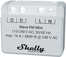
Shelly Wave PM Mini (EU)
Note: The product line known as "Shelly Qubino Wave" will now be referred to as "Shelly Wave". This name change will not impact the functionality of any devices. The only modification will be the use of the new name in all future documentation.
Device Identification
- Device name: Wave PM Mini
- EU Part number / Ordering Code: QMEM-0A1PC16EU
- Z-Wave Product type ID: 0x0007
- Z-Wave Product ID: 0x0081
- Z-Wave Manufacturer: Shelly Europe Ltd.
- Z-Wave Manufacturer ID: 0x0460
Terminology
- Device: In this document, the term “Device” refers to the Shelly Qubino device that is the subject of this guide.
- Gateway: A Z-Wave® gateway, also known as a Z-Wave® controller, main controller, primary controller, or hub. It serves as the central hub for a Z-Wave® smart home network. The term “gateway” is used in this document.
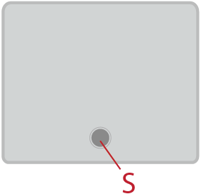
- S button: The Z-Wave® Service button, located on Z-Wave® devices, used for functions such as adding (inclusion), removing (exclusion), and resetting the device to factory defaults. The term “S button” is used in this document.
Short Description
The Shelly Wave PM Mini is a compact smart power meter that enables remote monitoring of electric appliance power consumption with a load capacity of up to 16 A.
Main Applications
- Residential
- MDU (Multi Dwelling Units – apartments, condominiums, hotels, etc.)
- Light commercial (small office buildings, small retail/restaurant/gas stations, etc.)
- Government/municipal
- University/college
Integrations
Shelly Wave devices are built on Z-Wave, the world’s leading smart home technology.
This means Shelly Wave works with all certified gateways supporting the Z-Wave communication protocol.
To ensure full compatibility and support for all device functions, we regularly test our devices with various Z-Wave gateways.
Simplified Internal Schematics
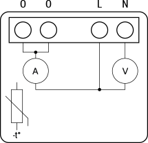
Device Electrical Interfaces
Inputs
- 2 power supply inputs on screw terminals: N, L
Outputs
- 2 output terminals with power measurement (on screw terminal)
Add-on Interface
- N/A
Connectivity
- Z-Wave: Unsecure, S0 Security, S2 Unauthenticated Security, S2 Authenticated Security
Safety Features
Overheat Protection
- Switches off its own relay
- Sends "Notification Report" to the gateway ("Overheat detected")
- LED reacts according to specified blinking pattern (check blinking mode for Overheat detected)
- Reset triggers: Power cycle, short press on S button, or pressing any switch/push-button connected to SW(SW1, SW2, …) terminals
- ✅ Note: Overheat protection is always active and cannot be disabled.
- For more details, see: Notification for Overheat Detected
Over-current Protection
- Device has internal over-current protection. If current exceeds 16A + 10% (Max switching current +10%) for more than 5 seconds:
- Switches off its own relay
- Sends "Notification Report" to the gateway ("Over-current detected")
- LED blinks per specified pattern (check LED blinking mode for Over-current detected)
- Reset triggers: Power cycle, short press on S button, or pressing any switch/push-button connected to SW(SW1, SW2, …) terminals
- ✅ Note: Over-current protection is always active and cannot be disabled.
- For more details, see: Notification for Over-current Detected
Over-voltage Protection
- Valid for standard 230 V AC power supply. If voltage exceeds 278 V AC (240 V AC + 15%) for more than 5 seconds:
- Switches off its own relay
- Sends "Notification Report" to the gateway ("Over-voltage detected")
- LED blinks per specified pattern (check LED blinking mode for Over-voltage detected)
- Reset triggers: Power cycle, short press on S button, or pressing any switch/push-button connected to SW(SW1, SW2, …) terminals
- ✅ Note: Over-voltage protection is always active and cannot be disabled.
- For more details, see: Notification for Over-voltage Detected
Supported Load Types
- Resistive (incandescent bulbs, heating devices)
- Capacitive (capacitor banks, electronic equipment, motor start capacitors)
- Inductive with RC Snubber (LED light drivers, transformers, fans, refrigerators, air conditioners)
User Interface
S Button and Operating Modes
- Normal mode
- Setting in progress mode
- Setting mode (with S button)
- Required to perform actions like inclusion, exclusion, or factory reset
- Limited time window; automatically reverts to Normal mode after completion
- Entering Setting Mode:
- Quickly press and hold the S button until the LED turns solid blue
- Additional quick press = menu navigation (infinite loop)
- Menu LED status times out after 10 seconds back to Normal state
S Button Functions
- Manually add the device to a Z-Wave network
- Manually remove the device from a Z-Wave network
- Factory reset the device
LED Signalisation
Normal Mode
Removed/Excluded: LED blinks blue in Mode 1 for 10 minutes after power cycle or S button press

Added/Included: LED blinks green in Mode 1 for 10 minutes after power cycle or S button press

Settings in Progress
- Factory Reset & Reboot:
- LED turns solid green (~1 sec), then blue and red blink rapidly (0.1s On / 0.1s Off) for ~2 sec
- Adding / Removing: LED blinks blue in Mode 2

- Firmware Update OTA: LED blinks blue and red in Mode 2

- Checking Power Supply (230V AC frequency or 24V DC voltage): LED blinks blue and red in Mode 5

Settings Mode with S Button
- Menu Selected (Add/Remove): LED stays blue for max 10 seconds
- Executing Add/Remove Process: LED blinks blue in Mode 3

- Menu Selected (Factory Reset): LED stays red for max 10 seconds
- Executing Factory Reset: LED blinks red in Mode 3

Alarm Mode
Over-current Detected:
- LED blinks red in Mode 4: 1x — 0.2s On / 0.2s Off → 2s Off → repeat

- LED blinks red in Mode 4: 1x — 0.2s On / 0.2s Off → 2s Off → repeat
Overheat Detected:
- LED blinks red in Mode 4: 2x — 0.2s On / 0.2s Off → 2s Off → repeat

- LED blinks red in Mode 4: 2x — 0.2s On / 0.2s Off → 2s Off → repeat
Power Supply Fault (AC frequency or DC voltage fault):
- LED blinks red in Mode 4: 3x — 0.2s On / 0.2s Off → 2s Off → repeat

- LED blinks red in Mode 4: 3x — 0.2s On / 0.2s Off → 2s Off → repeat
LED Blinking Modes
| Mode | Blink Pattern |
|---|---|
| Mode 1 | 0.5s On / 2s Off |
| Mode 2 | 0.5s On / 0.5s Off |
| Mode 3 | 0.1s On / 0.1s Off |
| Mode 4 | (1x–6x: 0.2s On / 0.2s Off) + 2s Off |
| Mode 5 | 0.2s On blue / 0.2s On red |
Specifications
| Parameter | Value |
|---|---|
| Power Supply | 110 – 240 V AC, 50/60 Hz |
| Power Consumption | < 0.3 W |
| Power Measurement (W) | Yes |
| External Protection | 16 A, tripping characteristic B or C 6 kA interrupting rating Energy limiting class 3 |
| Max Measurement Power | 3840 W |
| Max Measurement Current | 16 A |
| Overheating Protection | Yes |
| Distance (Indoor) | Up to 40 m (131 ft.) – depends on local conditions |
| Z-Wave® Repeater | Yes |
| CPU | Z-Wave® S800 |
| Z-Wave® Frequency Band | 868.4 MHz |
| Max RF Power Transmitted | < 25 mW |
| Dimensions (H × W × D) | 29 × 35 × 16 ±0.5 mm / 1.11 × 1.35 × 0.63 ±0.02 in |
| Weight | 13 ±1 g / 0.46 ±0.04 oz |
| Mounting | Wall box |
| Screw Terminal Max Torque | 0.4 Nm / 3.54 lbin |
| Conductor Cross Section | 0.5 to 1.5 mm² / 20 to 16 AWG |
| Conductor Stripped Length | 5 to 6 mm / 0.20 to 0.24 in |
| Shell Material | Plastic |
| Color | Light grey |
| Ambient Temperature | -20°C to 40°C / -5°F to 105°F |
| Humidity | 30% to 70% RH |
| Max Altitude | 2000 m / 6562 ft. |
Basic Wiring Diagram
| Wave PM Mini KB | Wave PM Mini SB KB |
|---|---|
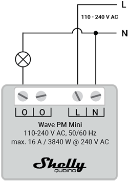 |  |
Legend
| Terminals | Meaning | Cables | Meaning |
|---|---|---|---|
| N | Neutral terminal | N | Neutral wire |
| L | Live terminal (110–240 V AC) | L | Live (110–240 V AC) wire |
| O | Load circuit output terminal | ||
| S | S button |
About Z-Wave®
Adding the Device to a Z-Wave® Network (Inclusion)
Note: All device outputs (O, O1, O2, etc.) will briefly turn on/off 1 second each if successfully added/removed.
Note: For Security 2 (S2) inclusion, you must enter the 5-digit PIN code printed on the Z-Wave® DSK label on the device and in packaging.
🔒 Important: Never lose the PIN code.
SmartStart Inclusion
- Scan the Z-Wave QR code on the device using a gateway with SmartStart support.
- Add the Device Specific Key (DSK) to the provisioning list.
- Connect the device to power.
- If the blue LED blinks in Mode 1 → device is not added.
- Automatic inclusion starts within seconds.
- Blue LED blinks in Mode 2 during inclusion.
- Green LED blinks in Mode 1 upon successful addition.
Adding with S Button
- Connect device to power.
- Check if blue LED blinks in Mode 1 → not added.
- Enable add/remove mode on the gateway.
- Press and hold S button until LED turns solid blue.
- Release, then press and hold (>2s) until blue LED blinks in Mode 3 → Learn mode starts.
- Blue LED blinks in Mode 2 during process.
- Green LED blinks in Mode 1 if successful.
⚠️ Note: Setting mode has a 10-second timeout before returning to Normal mode.
Adding with Switch/Push-button
- Connect device to power.
- Confirm blue LED blinks in Mode 1.
- Enable add/remove mode on gateway.
- Toggle the switch connected to any SW terminal (SW, SW1, SW2, ...) 3 times within 3 seconds.
- Blue LED blinks in Mode 2 during inclusion.
- Green LED blinks in Mode 1 if successful.
Learn mode: State allowing device to receive network info from gateway.
Removing the Device from a Z-Wave® Network (Exclusion)
Note: Device will be removed, but custom configurations remain intact.
Removing with S Button
- Connect device to power.
- Confirm green LED blinks in Mode 1 → device is added.
- Enable add/remove mode on gateway.
- Press and hold S button until LED turns solid blue.
- Release, then press and hold (>2s) until blue LED blinks in Mode 3 → LEARN MODE starts.
- Blue LED blinks in Mode 2 during removal.
- Blue LED blinks in Mode 1 if successful.
⚠️ Note: 10-second timeout in setting mode.
Removing with Switch/Push-button
- Connect device to power.
- Confirm green LED blinks in Mode 1.
- Enable add/remove mode on gateway.
- Toggle switch on any SW terminal 3 times within 3 seconds.
- Blue LED blinks in Mode 2 during removal.
- Blue LED blinks in Mode 1 if successful.
Factory Reset
General
After factory reset:
- All custom parameters, stored values (kWh, associations, routings, etc.) return to default
- HOME ID and NODE ID are deleted
- Use only when gateway is missing or inoperable
With S Button
- Press and hold S button until LED turns solid blue.
- Press S button repeatedly until LED turns solid red.
- Hold S button (>2s) until red LED blinks in Mode 3 → factory reset begins.
- During reset: LED turns solid green (~1s), then blue/red blink in Mode 3 (~2s).
- Blue LED blinks in Mode 1 → reset successful.
With Switch/Push-button
⚠️ Only possible within first minute after power-up.
- Connect device to power.
- Toggle switch on any SW terminal 5 times within 3 seconds.
- During reset: LED turns solid green (~1s), then blue/red blink in Mode 3 (~2s).
- Blue LED blinks in Mode 1 → reset successful.
Remotely via Gateway (Parameter 120)
Set Parameter No. 120 to 1 to trigger remote factory reset.
Z-Wave® Security and Device Specific Key (DSK)
The device supports Security 2 (S2) using AES-128 encryption, making Z-Wave® one of the most secure IoT platforms.
- Authenticated Control supported: Out-of-band DSK for inclusion
- Supports S2 Authenticated, Unauthenticated, and Unsecure inclusion
🔑 When using S2-enabled gateway, the 5-digit PIN Code from the DSK label is required.
Do not remove the DSK label. Keep the backup copy in packaging.
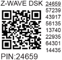
The first five digits are highlighted/underlined. DSK also includes a QR code.
Obfuscation Rule
When joining S2 Access Control or Authenticated Class, the public key is obfuscated by setting bytes 1–2 to 0x00.
The DSK can be used for out-of-band (OOB) authentication:
- Gateway scans QR code to read full DSK
- Matches against obfuscated public key received via RF
Z-Wave® Parameters
Parameter No. 36 – O (O1) Power Report on Change – Percentage
- Determines minimum power change to trigger report
- Size: 1 Byte
- Default: 50
- Values:
0– Reports disabled1–100– Change in power (%)
⚠️ Regardless of percentage, report won’t send more frequently than defined by Parameter 39.
Parameter No. 39 – Minimum Time Between Reports (O/O1)
- Minimum interval between power reports
- Size: 1 Byte
- Default: 30
- Values:
0– Reports disabled1–120(seconds) – Interval
⚠️ Related to Parameter 36
⚠️ Values < 30s may cause network congestion, slow response, reduced stability
Parameter No. 120 – Factory Reset
- Triggers factory reset and removes from Z-Wave network
- Advanced parameter (may be hidden under "Advanced" tag)
- Size: 1 Byte
- Default: 0
- Values:
0– Don’t reset1– Perform factory reset
Parameter No. 201 – Serial Number 1
- Part of device serial number
- Read-only, Advanced, hidden under "Advanced" tab
- Size: 4 Bytes
- Range:
0x00000000to0x7FFFFFFF
Parameter No. 202 – Serial Number 2
- Part of device serial number
- Same as above
Parameter No. 203 – Serial Number 3
- Part of device serial number
- Same as above
Z-Wave® Command Classes
- ASSOCIATION_V2 [S0, S2]*
- ASSOCIATION_GRP_INFO_V3 [S0, S2]*
- CONFIGURATION_V4 [S0, S2]*
- DEVICE_RESET_LOCALLY_V1 [S0, S2]*
- FIRMWARE_UPDATE_MD_V5 [S0, S2]*
- INDICATOR_V3 [S0, S2]*
- MANUFACTURER_SPECIFIC_V2 [S0, S2]*
- METER_V6 [S0, S2]*
- MULTI_CHANNEL_ASSOCIATION_V3 [S0, S2]*
- NOTIFICATION_V8 [S0, S2]*
- POWERLEVEL_V1 [S0, S2]*
- SECURITY_V1
- SECURITY_2_V1
- SUPERVISION_V1
- TRANSPORT_SERVICE_V2
- VERSION_V3 [S0, S2]*
- ZWAVEPLUS_INFO_V2
[S2]* = Security S2 Command Class
Z-Wave® Notifications Command Class
Overheat Detected
| Field | Value |
|---|---|
| Notification Type Name | Heat Alarm |
| Type Value | 0x04 |
| Event | State |
| Notification Name | Overheat detected |
| Name Value | 0x02 |
| Version | V2 |
| Device-specific | Yes |
| LED Signalisation | Refer to table |
| Device Reaction | Switch OFF all outputs + Send notification |
| Restore Action | Power cycle, S button press, or SW button press |
Over-current Detected O (O1)
| Field | Value |
|---|---|
| Notification Type Name | Power management |
| Type Value | 0x08 |
| Event | State |
| Notification Name | Over-current detected |
| Name Value | 0x06 |
| Version | V3 |
| LED Signalisation | Refer to table |
| Device Reaction | Switch OFF output O(O1) + Send notification |
| Restore Action | Power cycle, S button press, or SW button press |
AC Mains Disconnected
| Field | Value |
|---|---|
| Notification Type Name | Power management |
| Type Value | 0x08 |
| Event | State |
| Notification Name | AC mains disconnected |
| Name Value | 0x02 |
| Version | V2 |
| LED Signalisation | Refer to table |
| Device Reaction | Switch OFF all outputs + Send notification |
| Restore Action | Power cycle, S button press, or SW button press |
Over-voltage Detected
| Field | Value |
|---|---|
| Notification Type Name | Power management |
| Type Value | 0x08 |
| Event | State |
| Notification Name | Over-voltage detected |
| Name Value | 0x07 |
| Version | V3 |
| LED Signalisation | Refer to table |
| Device Reaction | Switch OFF all outputs + Send notification |
| Restore Action | Power cycle, S button press, or SW button press |
Z-Wave® Associations
Associations enable direct communication between devices without gateway involvement.
- Max 9 devices per group (fixed)
- Recommend ≤5 per group to avoid delays
- Lifeline Group (Group 1): Reserved for controllers, gateways, or interpretable devices
Lifeline Group (Root Device – Association Group 1 – Lifeline)
- INDICATOR_REPORT: LED status
- DEVICE_RESET_LOCALLY_NOTIFICATION: Triggered on request
- NOTIFICATION_REPORT: Triggered on:
- Overheat
- Over-current detected O(O1)
- Over-voltage detected
- AC mains disconnected
- METER_REPORT: Triggered by load power consumption (based on Parameters 36 & 39)
Z-Wave® Important Disclaimer
Z-Wave® wireless communication may not be 100% reliable.
Do not rely solely on this device for life-critical applications or high-value assets.
If device isn't recognized or behaves incorrectly, manually verify device type and ensure gateway supports Z-Wave Plus™ multi-level devices.
Troubleshooting
For help, visit: Shelly Support Portal
Compatibility
| Gateway | On/Off | SW On/Off | Notes |
|---|---|---|---|
| Home Assistant | ✅ | ✅ | |
| Fibaro HC 3 / Z-Wave engine 3 | ✅ | ✅ | |
| Homey | ✅ | ✅ | |
| Homee Cube Gen 7 | ✅ | ✅ | |
| Homee Cube Gen 5 | ✅ | ⚪ | |
| SmartThings | ✅ | ✅ | With Shelly Wave edge driver |
| Vera Ezlo | ✅ | ✅ | |
| Cozify | ✅ | ✅ |
⚪ = Partially supported
❌ = Not working
🟨 = Not tested
🟩 = Working
📝 = To be done
Legend
| Symbol | State |
|---|---|
| ✅ | Working / Possible |
| ⚪ | Partially |
| ❌ | Not Working / Not Possible |
| 🟨 | Not Tested |
| 📝 | To be done |
Function Meanings
| Function | Meaning / Tested |
|---|---|
| On/Off | Responds to app UI On/Off command |
| SW On/Off | Reports On/Off changes via SW input |
| Dimming | Responds to app UI dimming command |
| SW Dimming | Reports dimming state change via SW input |
| Watts | Reports watts (unsolicited) |
| kWh | Reports kWh (unsolicited) |
| Up/Down | Responds to app UI Up/Down command |
| SW Up/Down | Reports Up/Down changes via SW input |
| Slats | Slats respond to app UI command |
| SW Slats | Slats report changes made via SW |
| D control | Reports scene commands (single/double press, etc.) in detached mode |
| D Binary | Reports binary On/Off via SW input in detached mode |
| Sensor # | Sensor reported in gateway; note type |
Gateway Guides
Useful guides available at: Shelly Knowledge Base – Z-Wave
Compliance
- Shelly Wave PM Mini Multilingual EU Declaration of Conformity (232)
- Wave PM Mini UK PSTI ACT Statement of Compliance
Compliance Archive
- Wave PM Mini Multilingual EU Declaration of Conformity (166)
- Wave PM Mini Multilingual EU Declaration of Conformity (39)