Shelly Wave Shutter
Note: The product line known as "Shelly Qubino Wave" will now be referred to as "Shelly Wave". This name change will not impact the functionality of any devices. The only modification will be the use of the new name in all future documentation.
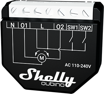
Device: Wave Shutter
- AUS Part number / Ordering Code: QNSH-001P10AU
- Z-Wave Product type ID: 0x0003
- Z-Wave Product ID: 0x0082
- Z-Wave Manufacturer: Shelly Europe Ltd.
- Z-Wave Manufacturer ID: 0x0460
Terminology
- Device – In this document, the term “Device” refers to the Shelly Qubino device covered by this guide.
- Gateway – A Z-Wave® gateway (also called a Z-Wave® controller, main controller, primary controller, or hub) acts as the central hub for a Z-Wave® smart home network. The term "gateway" is used throughout this document.
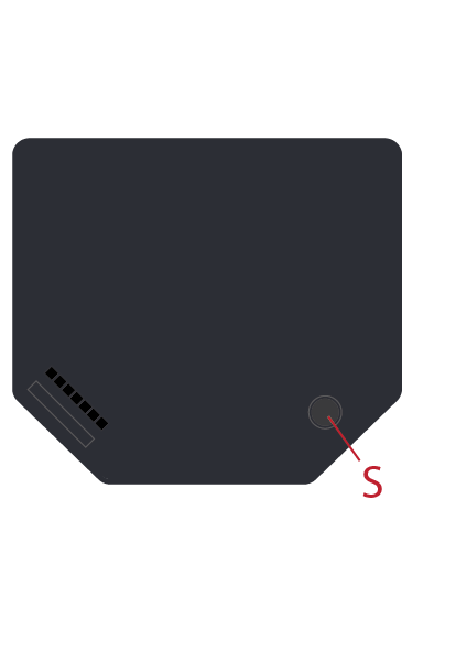
- S button – The Z-Wave® Service button located on Z-Wave® devices, used for inclusion/exclusion and factory reset. The term "S button" is used here.
- Adding/Inclusion – The process of adding a Z-Wave device to a Z-Wave network via the gateway. Words like included, added, etc., are used interchangeably.
- Removing/Exclusion – The process of removing a Z-Wave device from a Z-Wave network. Terms such as excluded, removed, etc., are used.
- Blind – Refers to any window treatment including venetian blinds, roller blinds/screens, roller shutters, vertical blinds, curtains, integral venetian blinds, pleated blinds, awnings, etc. Additionally, Wave Shutter can control window motors, projector screens, or any bi-directional AC motor.
Short Description
The device enables remote control of motorized blinds, roller shutters, venetian blinds, awnings, and similar systems. It also measures the power consumption of the connected load.
✅ Recommendation: Use only motors equipped with electronic or mechanical limit switches. Ensure limit switches are correctly set before connecting the device.
Manual Operation for Shutter
With Momentary Switch (Parameter No. 71 = 0, Parameter No. 1 = 0)
| Action on Push-Button | Blind Not Moving | Blind Moving Up | Blind Moving Down | Slats Tilting (Venetian) |
|---|---|---|---|---|
| Short press (< 0.5s) UP | Starts moving up | Stops movement | Stops movement | No action |
| Short press (< 0.5s) DOWN | Starts moving down | Stops movement | Stops movement | No action |
| Long press (> 0.5s) UP | Starts moving up; tilts slats if venetian | Moving | Moving | Tilts slats → moves up |
| Long press (> 0.5s) DOWN | Starts moving down; tilts slats if venetian | Moving | Moving | Tilts slats → moves down |
| Release after long press | No action | Stops movement | Stops movement | Stops tilting |
With Toggle Switch (Parameter No. 71 = 0, Parameter No. 1 = 1)
- Press toggle switch on SW1 (up): initiates upward movement until released.
- Press toggle switch on SW2 (down): initiates downward movement until released.
With Venetian Blinds + Momentary Switch (Parameter No. 71 = 1, Parameter No. 1 = 0)
- Short press (< 0.5s): triggers blind movement.
- Long press (> 0.5s): triggers slats rotation (0–100% or 100–0%).
| Action on Push-Button | Blind Not Moving | Blind Moving Up | Blind Moving Down | Slats Tilting (Venetian) |
|---|---|---|---|---|
| Short press UP | Start moving up | Stop movement | Stop movement | Stop tilting |
| Short press DOWN | Start moving down | Stop movement | Stop movement | Stop tilting |
| Long press UP | Start tilting slats | No action | No action | Tilts to end |
| Long press DOWN | Start tilting slats | No action | No action | Tilts to end |
| Release after long press | No action | Stop movement | Stop movement | Stop tilting |
With Venetian Blinds + Toggle Switch (Parameter No. 71 = 1, Parameter No. 1 = 1)
- Press toggle SW1 (up): move up until release.
- Press toggle SW2 (down): move down until release.
- If slats at 100% and UP pressed quickly → move up.
- If slats at 0% and DOWN pressed quickly → move down.
Slats Positioning
To achieve precise slat positioning:
- When setting an intermediate position, slats first rotate to 100%, then back to target.
- During downward movement: when limit reached or stopped, slats rotate to 100% then return to previous position.
- During upward movement: upon stop, slats return to prior position.
Main Applications
- Residential
- MDU (Multi Dwelling Units – apartments, condos, hotels, etc.)
- Light Commercial (small offices, retail, restaurants, gas stations)
- Government/Municipal
- University/College
Integrations
Shelly Qubino Wave devices are built on Z-Wave, the world’s leading smart home technology.
They work with all certified gateways supporting Z-Wave communication.
We regularly test compatibility across various Z-Wave gateways to ensure full functionality.
Simplified Internal Schematics
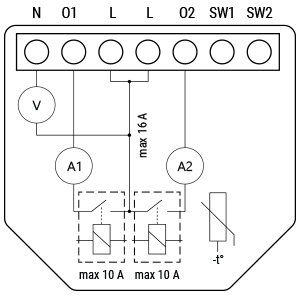
Device Electrical Interfaces
Inputs
- 2 switch/button inputs on screw terminals
- 3 power supply inputs on screw terminals: N and L
Outputs
- 2 relay outputs with power measurement on screw terminals
Connectivity
Z-Wave: Unsecure, S0 Security, S2 Unauthenticated Security, S2 Authenticated Security
Safety Features
- Over-load detection
- Overheat detection
Supported Load Types
- Resistive (incandescent bulbs, heating devices)
- Capacitive (capacitor banks, electronic equipment, motor start capacitors)
- Inductive with RC Snubber (LED drivers, transformers, fans, refrigerators, air conditioners)
User Interface
S Button and Operating Modes
- Normal mode
- Setting in progress mode
- Setting mode (with S button)
- Required to perform actions like inclusion, exclusion, or factory reset.
- Limited time: automatically returns to Normal mode after 10 seconds.
- To enter: press and hold S button until LED turns solid blue.
- Additional quick press cycles through menu (infinite loop).
- Timeout: 10 seconds before returning to normal state.
S Button Functions
- Manually add device to Z-Wave network
- Manually remove device from Z-Wave network
- Factory reset device
Functionality
Automatic Calibration
The device learns the position of the limit switches during calibration.
⚠️ Important Note: For correct operation, automatic calibration must be performed!
⚠️ Critical Requirement: Motor must have electronic or mechanical limit switches properly set before calibration.
Shutter Positioning Calibration (Shutter Mode)
Set Parameter No. 71 = 0
Calibration with Gateway
- Add device to Z-Wave network (via inclusion).
- Set Parameter No. 78 (Forced Shutter Calibration) to
1. - Device performs full cycle: up → down → up → down to 50%.
- Check Parameter No. 78: value should be
2(success),3(not calibrated), or4(error). - Confirm yellow LED is not blinking.
❗ If value is 3 or 4: verify full cycle completion, correct limit switch settings, and proper wiring.
Calibration with Push-Button (SW1)
- Move blind to top (upper) position.
- Press SW1 four times within 3 seconds.
- Device starts calibration and completes 4 cycles (up, down, up, down to 50%).
- No time limit — safe to repeat.
Calibration with S Button
- Enter Setting mode: short press S button.
- Hold S button until yellow LED appears (calibration selected).
- Press and hold S button for >2 seconds to start calibration.
- Confirm yellow LED is not blinking.
❗ If yellow LED still blinks: check full cycle, limit switches, and wiring.
Slats Tilting Position Calibration (Venetian Mode)
Set Parameter No. 71 = 1
After enabling Venetian mode, calibrate slat tilt position:
- Perform standard shutter calibration (as above).
- Set Parameter No. 71 =
1("Venetian blinds"). - Default rotation time: 1.5 seconds.
- Too long? → Decrease Parameter No. 72.
- Too short? → Increase Parameter No. 72.
- Repeat step 3 until slat position is accurate.
✅ Tip: Correct timing ensures slats don’t move blinds up/down during rotation.
LED Signalization
General Rules
- Press S button once to toggle between Normal and Setting modes.
- Solid LED = Setting mode (auto-exits after 10 sec).
- LED turns off after 30 min (unless woken by S button or power cycle).
Normal Mode LED Status
| Condition | LED Behavior |
|---|---|
| Removed/Excluded / Not Calibrated | Blinking blue (10 min after power-up or S press) |
| Removed/Excluded / Calibrated | Blinking blue + yellow (30 min after power-up, 10 min after S press) |
| Added/Included / Not Calibrated | Blinking green (10 min after power-up or S press) |
| Added/Included / Calibrated | Blinking green + yellow (30 min after power-up, 10 min after S press) |
Settings in Progress
| Action | LED Behavior |
|---|---|
| Factory Reset & Reboot | Solid green (~1s), then blinking blue+red (0.1s on/off, ~2s) |
| Adding/Removing | Blinking blue (Mode 2) |
| Shutter Calibration | Blinking yellow (Mode 2) |
Settings Mode with S Button
| Menu Selection | LED Behavior |
|---|---|
| Adding/Removing | Solid blue (max 10 sec) |
| Adding/Removing (during process) | Blinking blue (Mode 3) |
| Factory Reset | Solid red (max 10 sec) |
| Factory Reset (during process) | Blinking red (Mode 3) |
| Calibration | Solid yellow (max 10 sec) |
| Calibration (during process) | Blinking yellow (Mode 3) |
Alarm Mode
| Alarm Type | LED Behavior |
|---|---|
| Over-current detected | Blinking red: 1x (0.2s on/off), 2s off (repeats) |
| Overheat detected | Blinking red: 2x (0.2s on/off), 2s off (repeats) |
| Power supply fault | Blinking red: 3x (0.2s on/off), 2s off (repeats) |
LED Blinking Modes
| Mode | Blink Pattern |
|---|---|
| Mode 1 | 0.5s On / 2s Off |
| Mode 2 | 0.5s On / 0.5s Off |
| Mode 3 | 0.1s On / 0.1s Off |
| Mode 4 | (1–6x: 0.2s On/Off) + 2s Off |
| Mode 5 | 0.2s Blue / 0.2s Red |
Specifications
| Feature | Value |
|---|---|
| Power Supply | 110–240 V AC, 50/60 Hz |
| Power Consumption | < 0.3 W |
| Power Measurement | Yes |
| Max Switching Voltage AC | 240 V |
| Max Switching Current AC | 10 A per channel |
| Overheating Protection | Yes |
| Overload Protection | Yes |
| Range | Up to 40 m indoors (131 ft.) |
| Z-Wave® Repeater | Yes |
| CPU | Z-Wave® S800 |
| Z-Wave® Frequency Band | 919.8 MHz |
| Max RF Power | < 25 mW |
| Dimensions (H x W x D) | 37 × 42 × 16 ± 0.5 mm (1.46 × 1.65 × 0.63 ± 0.02 in) |
| Weight | 29 g |
| Mounting | Wall console |
| Screw Terminal Torque | 0.4 Nm / 3.5 lbin |
| Conductor Cross Section | 0.5–1.5 mm² / 20–16 AWG |
| Stripped Length | 5–6 mm / 0.20–0.24 in |
| Shell Material | Plastic |
| Color | Black |
| Ambient Temperature | -20°C to 40°C (-5°F to 105°F) |
| Humidity | 30% to 70% RH |
| Max Altitude | 2000 m / 6562 ft. |
Basic Wiring Diagram
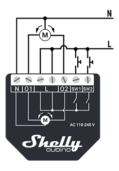
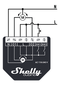
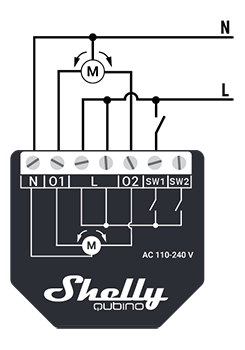
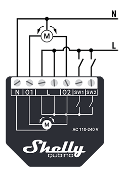
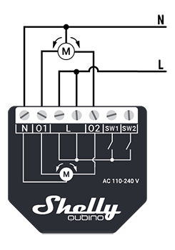
Legend
| Terminal | Description | Wire | Description |
|---|---|---|---|
| N | Neutral terminal | N | Neutral wire |
| L | Live terminal (110–240 V AC) | L | Live (110–240 V AC) wire |
| O1 | Output for motor UP (open) | — | — |
| O2 | Output for motor DOWN (close) | — | — |
| SW1 | Input for switch/push-button UP (open) | — | — |
| SW2 | Input for switch/push-button DOWN (close) | — | — |
About Z-Wave
Adding to Z-Wave Network (Inclusion)
🔔 Note: The blind will move 2s up/down after successful addition/removal.
🔐 Security 2 (S2): Requires PIN code (5 underlined digits) from the DSK label on the device or packaging.
SmartStart Inclusion
- Scan QR code on device using gateway app.
- Add Device Specific Key (DSK) to provisioning list.
- Connect device to power.
- If blue LED blinks slowly → not added.
- Device auto-adds within minutes.
- Blue LED blinks faster during inclusion.
- Green LED blinks slowly if successful.
Inclusion with S Button
- Connect to power.
- Check for slow blue blink → not added.
- Enable add/remove mode on gateway.
- Press and hold S button until LED turns solid blue.
- Release, then press and hold (>2s) until blue LED blinks slowly → starts Learn mode.
- Blue LED blinks faster during inclusion.
- Green LED blinks slowly if successful.
⏱️ Setting mode timeout: 10 seconds.
Inclusion with Switch/Push-Button
- Connect to power.
- Check for slow blue blink.
- Enable add/remove mode on gateway.
- Toggle switch/push-button connected to SW terminal 3 times within 3 seconds → enters Learn mode.
- Blue LED blinks faster during inclusion.
- Green LED blinks slowly if successful.
📌 Learn mode: State allowing device to receive network info from gateway.
Removing from Z-Wave Network (Exclusion)
🛑 Note: Custom parameters remain unchanged after removal.
Removal with S Button
- Connect to power.
- Check for slow green blink → added.
- Enable add/remove mode on gateway.
- Press and hold S button until LED turns solid blue.
- Release, then press and hold (>2s) until blue LED blinks slowly → starts Learn mode.
- Blue LED blinks faster during removal.
- Blue LED blinks slower if successful.
Removal with Switch/Push-Button
- Connect to power.
- Check for slow green blink.
- Enable add/remove mode on gateway.
- Toggle switch/push-button 3 times within 3 seconds → enters Learn mode.
- Blue LED blinks faster during removal.
- Blue LED blinks slower if successful.
Factory Reset
💡 After reset: All custom settings, associations, kWh data, routing, etc., revert to defaults. HOME ID and NODE ID deleted.
With S Button
- Press and hold S button until LED turns solid blue.
- Press multiple times until LED turns solid red.
- Press and hold (>2s) until red LED blinks fast → starts reset.
- LED turns solid green (~1s), then blue+red blink fast (~2s).
- Blue LED blinks slowly if successful.
With Switch/Push-Button
⚠️ Only possible within first minute after power-up.
- Connect to power.
- Toggle switch/push-button 5 times within 3 seconds.
- LED turns solid green (~1s), then blue+red blink fast (~2s).
- Blue LED blinks slowly if successful.
Z-Wave Security and Device Specific Key (DSK)
- Supports latest Security 2 (S2) with AES-128 encryption.
- S2 ensures highest security for IoT networks.
- Requires S2-enabled gateway.
Authentication Options
- Out-of-band DSK for inclusion
- Compatible with most implementations
DSK Label & QR Code
- Unique DSK printed on side of device and inside packaging.
- First five digits highlighted/underlined → PIN code.
- QR code visible on label.
🔒 Never remove DSK label! Keep backup in packaging.
Z-Wave Parameters
Unable to render
{include}– Page not found.
Z-Wave Command Classes
COMMAND_CLASS_ZWAVEPLUS_INFO_V2COMMAND_CLASS_SWITCH_MULTILEVEL_V4COMMAND_CLASS_ASSOCIATION_3COMMAND_CLASS_MULTI_CHANNEL_ASSOCIATION_V4COMMAND_CLASS_ASSOCIATION_GRP_INFO_V3COMMAND_CLASS_NOTIFICATION_V9COMMAND_CLASS_TRANSPORT_SERVICE_V2COMMAND_CLASS_VERSION_V3COMMAND_CLASS_MANUFACTURER_SPECIFIC_V2COMMAND_CLASS_DEVICE_RESET_LOCALLY_V1COMMAND_CLASS_INDICATOR_V4COMMAND_CLASS_POWERLEVEL_V1COMMAND_CLASS_SECURITY_V1COMMAND_CLASS_SECURITY_2_V1COMMAND_CLASS_MULTI_CHANNEL_V4COMMAND_CLASS_SUPERVISION_V2COMMAND_CLASS_FIRMWARE_UPDATE_MD_V7COMMAND_CLASS_CONFIGURATION_V4COMMAND_CLASS_SWITCH_BINARY_V2COMMAND_CLASS_APPLICATION_STATUS_V2COMMAND_CLASS_METER_V6
Endpoint 1
- Device Class: BASIC_TYPE_ROUTING_SLAVE, GENERIC_TYPE_SWITCH_MULTILEVEL, SPECIFIC_TYPE_CLASS_B_MOTOR_CONTROL
- Supported Command Classes: All listed above
Endpoint 2
- Only active when Parameter No. 71 = 1
- Same device class and command classes as Endpoint 1
Z-Wave Notifications Command Class
| Notification Type | Event |
|---|---|
| Power Management (0x08) | Over-load detected (0x08) |
| Heat Alarm (0x04) | Overheat detected (0x02) |
🚨 Automatically disables output and sends notification upon overload or overheat.
Z-Wave Associations
Association Group 1 – Lifeline
- Max nodes: 1 (only gateway allowed)
- Reports status changes, overloads, overheat, and meter readings.
- Triggered by:
DEVICE_RESET_LOCALLY_NOTIFICATION,SWITCH_BINARY_REPORT,NOTIFICATION_REPORT,METER_REPORT
Association Group 2
- Max nodes: 9
- Triggers on SW1/SW2 input (Shutter mode)
- Commands:
SWITCH_MULTILEVEL_START_LEVEL_CHANGE,SWITCH_MULTILEVEL_STOP_LEVEL_CHANGE - Recommended: push buttons
Association Group 3
- Max nodes: 9
- Triggers on SW1/SW2 input (Venetian mode)
- Same commands as Group 2
- Recommended: push buttons
Association Group 4
- Max nodes: 16
- Sends
BASIC_SET ONwhen moving up,OFFwhen moving down - Used to trigger associated devices (e.g., lights)
Association Group 5
- Max nodes: 16
- Sends
BASIC_SET OFFat top,ONat bottom - Used for status feedback
Association Groups 6 & 7
- Same as Groups 2 & 3 respectively
- Apply to both Shutter and Venetian modes
Important Disclaimer
Z-Wave wireless communication may not always be 100% reliable. Do not rely solely on this device for life-critical or high-value applications.
If device isn't recognized or behaves incorrectly, manually adjust device type and confirm gateway supports Z-Wave Plus™ multi-channel devices.
Troubleshooting
Visit our support portal: https://support.shelly.cloud/
Compatibility with Gateways
| Gateway | Up | Down | SW Up | SW Down | W | kWh | Slats | SW Slats | Notes |
|---|---|---|---|---|---|---|---|---|---|
| Home Assistant | ✅ | ✅ | ✅ | ✅ | ✅ | ✅ | ✅ | ✅ | |
| Fibaro HC 3 / Z-Wave engine 3 | ✅ | ✅ | ✅ | ✅ | ✅ | ✅ | ✅ | ✅ | |
| Homey | ✅ | ✅ | ✅ | ✅ | ✅ | ✅ | ✅ | ✅ | |
| Homee Cube Gen 7 | ✅ | ✅ | ✅ | ✅ | ✅ | ❌ | ⚠️ | ⚠️ | *1 |
| Homee Cube Gen 5 | ✅ | ✅ | ⚠️ | ⚠️ | ⚠️ | ⚠️ | ⚠️ | ⚠️ | *1, *2, *3 |
| Smart Things | ✅ | ✅ | ✅ | ❌ | ⚠️ | ⚠️ | With Shelly Wave edge driver *4 | ||
| Vera Ezlo | ✅ | ✅ | ✅ | ✅ | ✅ | ✅ | ✅ | ✅ | |
| Cozify | ✅ | ✅ | ✅ | ✅ | ✅ | ✅ | ✅ | ✅ |
Notes
- *1: No widget to control slats
- *2: UI reports only via buttons; slider doesn't refresh state
- *3: State updates only after stop button press
- *4: Device sent to position but position not reported
Legend
| Symbol | Meaning |
|---|---|
| ✅ | Working / Possible |
| ⚠️ | Partially |
| ❌ | Not Working / Not Possible |
| N/T | Not Tested |
| TBD | To Be Done |
Function Meanings
| Function | Meaning |
|---|---|
| On/Off | Responds to app UI On/Off command |
| SW On/Off | Reports On/Off via SW input |
| Dimming | Responds to app UI dimming command |
| SW Dimming | Reports dimming state via SW input |
| Watts | Reports watts unsolicited |
| kWh | Reports kWh unsolicited |
| Up/Down | Responds to app UI Up/Down |
| SW Up/Down | Reports Up/Down via SW input |
| Slats | Responds to app UI slats command |
| SW Slats | Reports slats change via SW input |
| D Control | Detached mode: reports scene commands |
| D Binary | Detached mode: reports binary On/Off via SW |
| Sensor # | Sensor visualized in gateway; note type |
Components and APIs
Depends on the gateway used.