Shelly Wave i4
Note: The product line known as "Shelly Qubino Wave" will now be referred to as "Shelly Wave". This name change will not impact the functionality of any devices. The only modification will be the use of the new name in all future documentation.
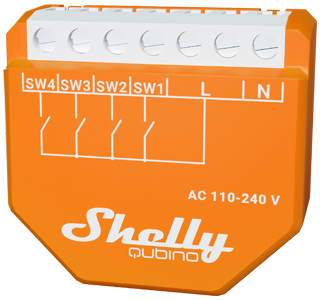
Device: Wave i4
- EU Part number / Ordering Code: QNSN-0A24XEU
- Z-Wave Product type ID: 0x0009
- Z-Wave Product ID: 0x0081
- Z-Wave Manufacturer: Shelly Europe Ltd.
- Z-Wave Manufacturer ID: 0x0460
Terminology
- Device – In this document, the term “Device” refers to the Shelly Qubino device that is the subject of this guide.
- Gateway – A Z-Wave® gateway, also referred to as a Z-Wave® controller, Z-Wave® main controller, Z-Wave® primary controller, or Z-Wave® hub, etc., is a device that serves as a central hub for a Z-Wave® smart home network. The term “gateway” is used in this document.
- S button – The Z-Wave® Service button, located on Z-Wave® devices and used for various functions such as adding (inclusion), removing (exclusion), and resetting the device to its factory default settings. The term "S button" is used in this document.
- Adding/Inclusion – The process of adding a Z-Wave device to a Z-Wave network – gateway. Words like included, added, etc., are used in this context.
- Removing/Exclusion – The process of removing a Z-Wave device from a Z-Wave network – gateway. Words like excluded, removed, etc., are used in this context.
- Blind – Refers to any kind of window treatment, such as venetian blinds, roller blinds (screens), roller shutters, vertical window blinds, curtains, integral venetian blinds, pleated blinds, awnings, etc. Additionally, Wave Shutter can control window motors, projector screens, or any type of bi-directional AC motor.
Short Description
The Device is a 4-digital inputs module (110–240 V AC) that controls other devices within the Z-Wave network. It enables manual activation or deactivation of scenes through a switch/push-button.
Switch/Push-Button Connected to Input Terminal SW1
The device supports Central Scene Command Class. When a button is single pressed, double pressed, held and released, it transmits a scene notification with scene number (1, 2, 3, or 4).
NOTE: Switch type is not supported for triggering central scene notifications.
Push-Button Connected to Input Terminal SW1
If SW1 is configured as a push-button:
- Scene number =
0x01
Actions:
- Short press: Sends Central scene notification “Key pressed 1 time = 0x00” with scene number
0x01, and sends command to associated devices in Group 4 (see Z-Wave Association). - 2x Short press: Sends Central scene notification “Key pressed 2 times = 0x00”.
- Press and hold: Sends Central scene notification “Key held down = 0x02”, and sends command to associated devices in Group 5 (see Z-Wave Association).
- Release: Sends Central scene notification “Key released = 0x01”, and sends command to associated devices in Group 5 (see Z-Wave Association).
If SW1 is configured as a switch:
- Change switch position once: Sends command to associated devices in Groups 4 and 5 (see Z-Wave Association).
If SW1 is configured as a switch-memory:
- Switching to Close contact: Sends command to associated devices in Groups 4 and 5 based on switch state.
- Switching to Open contact: Sends command to associated devices in Groups 4 and 5 based on switch state.
Switch/Push-Button Connected to Input Terminal SW2
If SW2 is configured as a push-button:
- Scene number =
0x02
Actions:
- Short press: Sends Central scene notification “Key pressed 1 time = 0x00” with scene number
0x02, and sends command to associated devices in Group 6 (see Z-Wave Association). - 2x Short press: Sends Central scene notification “Key pressed 2 times = 0x00”.
- Press and hold: Sends Central scene notification “Key held down = 0x02”, and sends command to associated devices in Group 7 (see Z-Wave Association).
- Release: Sends Central scene notification “Key released = 0x01”, and sends command to associated devices in Group 7 (see Z-Wave Association).
If SW2 is configured as a switch:
- Change switch position once: Sends command to associated devices in Groups 6 and 7 (see Z-Wave Association).
If SW2 is configured as a switch-memory:
- Switching to Close contact: Sends command to associated devices in Groups 6 and 7 based on switch state.
- Switching to Open contact: Sends command to associated devices in Groups 6 and 7 based on switch state.
Switch/Push-Button Connected to Input Terminal SW3
If SW3 is configured as a push-button:
- Scene number =
0x03
Actions:
- Short press: Sends Central scene notification “Key pressed 1 time = 0x00” with scene number
0x03, and sends command to associated devices in Group 8 (see Z-Wave Association). - 2x Short press: Sends Central scene notification “Key pressed 2 times = 0x00”.
- Press and hold: Sends Central scene notification “Key held down = 0x02”, and sends command to associated devices in Group 9 (see Z-Wave Association).
- Release: Sends Central scene notification “Key released = 0x01”, and sends command to associated devices in Group 9 (see Z-Wave Association).
If SW3 is configured as a switch:
- Change switch position once: Sends command to associated devices in Groups 8 and 9 (see Z-Wave Association).
If SW3 is configured as a switch-memory:
- Switching to Close contact: Sends command to associated devices in Groups 8 and 9 based on switch state.
- Switching to Open contact: Sends command to associated devices in Groups 8 and 9 based on switch state.
Switch/Push-Button Connected to Input Terminal SW4
If SW4 is configured as a push-button:
- Scene number =
0x04
Actions:
- Short press: Sends Central scene notification “Key pressed 1 time = 0x00” with scene number
0x04, and sends command to associated devices in Group 10 (see Z-Wave Association). - 2x Short press: Sends Central scene notification “Key pressed 2 times = 0x00”.
- Press and hold: Sends Central scene notification “Key held down = 0x02”, and sends command to associated devices in Group 11 (see Z-Wave Association).
- Release: Sends Central scene notification “Key released = 0x01”, and sends command to associated devices in Group 11 (see Z-Wave Association).
If SW4 is configured as a switch:
- Change switch position once: Sends command to associated devices in Groups 8 and 9 (see Z-Wave Association).
If SW4 is configured as a switch-memory:
- Switching to Close contact: Sends command to associated devices in Groups 10 and 11 based on switch state.
- Switching to Open contact: Sends command to associated devices in Groups 10 and 11 based on switch state.
Main Applications
- Residential
- MDU (Multi Dwelling Units – apartments, condominiums, hotels, etc.)
- Light commercial (small office buildings, small retail/restaurant/gas station, etc.)
- Government/municipal
- University/college
Integrations
Shelly Qubino Wave devices are developed on the world's leading technology for smart homes – Z-Wave.
This means Shelly Qubino Wave works with all certified gateways supporting the Z-Wave communication protocol.
To ensure full functionality, refer to the Compatibility with Gateways section for detailed compatibility reports.
Simplified Internal Schematics
N/A
Device Electrical Interfaces
Inputs
- 1 switch/button input on screw terminal
- 2 switch/button inputs on screw terminal
- 3 switch/button inputs on screw terminal
- 4 switch/button inputs on screw terminal
- 3 power supply inputs on screw terminals: N, L
Outputs
N/A
Connectivity
Z-Wave – Unsecure, S0 Security, S2 Unauthenticated Security, S2 Authenticated Security
Safety Features
Overheat Protection
- Automatically switches off its own relay
- Sends Notification Report to the Gateway ("Overheat detected")
- LED lights react as specified (check blinking mode for Overheat detected)
Any of the following activities reset this alarm:
- Power cycle
- Short press on S button
- Press any switch/push-button connected to any SW (SW, SW1, SW2, …) terminal
NOTE: Overheat protection is always active and cannot be disabled.
Additional details under Notification for Overheat Detected
Supported Load Types
N/A
User Interface
S Button and Operating Modes
- Normal mode
- Setting in progress mode
- Setting mode (with S button)
- Required to start procedures like adding/inclusion, removing/exclusion, factory reset, etc.
- Limited operation time; automatically returns to Normal mode after completion.
- Entering Setting mode:
- Quickly press and hold the S button until the LED turns solid blue
- An additional quick press changes menu in an infinite loop
- Menu LED status has a 10-second timeout before returning to Normal state
S Button Functions
- Manually add the Device to a Z-Wave network
- Manually remove the Device from a Z-Wave network
- Factory Reset the Device
LED Signalisation
Normal Mode
- Removed/Excluded: LED blinks blue in Mode 1 for 10 minutes after power cycle or S button press

- Added/Included: LED blinks green in Mode 1 for 10 minutes after power cycle or S button press

Settings in Progress
- Factory reset and reboot:
- LED turns solid green (~1 sec), then blue and red blink rapidly (0.1s On / 0.1s Off) for ~2 sec
- Adding / Removing: LED blinks blue in Mode 2

- Firmware updating OTA: LED blinks blue and red in Mode 2

- Checking power supply (230V AC or 24V DC): LED blinks blue and red in Mode 5

Settings Mode with S Button
- Menu selected (Add/Remove): LED stays solid blue (max 10 sec)
- During Add/Remove process: LED blinks blue in Mode 3

- Menu selected (Factory Reset): LED stays solid red (max 10 sec)
- During Factory Reset process: LED blinks red in Mode 3

Alarm Mode
- Overheat detected: LED blinks red in Mode 4 — pattern: (1x to 6x: 0.2s On / 0.2s Off) + 2s Off, repeating

LED Blinking Modes
| Mode | Description |
|---|---|
| Mode 1 | 0.5s On / 2s Off |
| Mode 2 | 0.5s On / 0.5s Off |
| Mode 3 | 0.1s On / 0.1s Off |
| Mode 4 | (1x to 6x: 0.2s On / 0.2s Off) + 2s Off |
| Mode 5 | 0.2s On (blue) / 0.2s On (red) |
Specifications
| Parameter | Value |
|---|---|
| Power supply AC | 110 – 240 V AC, 50/60 Hz |
| Power supply DC | No |
| Power consumption | < 0.2 W |
| Overload protection | No |
| Power measurement | No |
| Working without neutral line | No |
| Number of inputs | 4 |
| Distance | Up to 40 m indoors (131 ft.), depends on local conditions |
| Z-Wave® repeater | Yes |
| CPU | Z-Wave® S800 |
| Z-Wave® frequency band | 868.4 MHz |
| Max radio frequency power | < 25 mW |
| Size (H x W x D) | 37 × 42 × 16 ±0.5 mm / 1.46 × 1.65 × 0.63 ±0.02 in |
| Weight | 17 g / 0.6 oz |
| Mounting | Wall console |
| Screw terminals max torque | 0.4 Nm / 3.5 lbin |
| Conductor cross section | 0.5 to 1.5 mm² / 20 to 16 AWG |
| Conductor stripped length | 5 to 6 mm / 0.20 to 0.24 in |
| Shell material | Plastic |
| Color | Orange |
| Ambient temperature | -20°C to 40°C / -5°F to 105°F |
| Humidity | 30% to 70% RH |
Basic Wiring Diagram
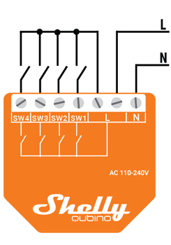
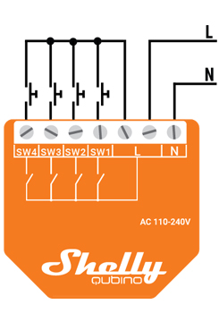
Legend
| Terminals | Description |
|---|---|
| N | Neutral terminal |
| L | Live terminal (110–240 V AC) |
| SW 1 | Switch/push-button input terminal |
| SW 2 | Switch/push-button input terminal |
| SW 3 | Switch/push-button input terminal |
| SW 4 | Switch/push-button input terminal |
About Z-Wave
Adding the Device to a Z-Wave® Network (Inclusion)
Note! The blind connected to the Device will move 2 seconds up/down if the Device is successfully added/removed from a Z-Wave® network.
Note! For Security 2 (S2) inclusion, a dialog appears asking for the 5-digit PIN code printed on the Z-Wave® DSK label (on the device and in packaging).
IMPORTANT: Do not lose the PIN code.
SmartStart Inclusion
- Scan the Z-Wave QR Code on the device with a gateway supporting SmartStart.
- No further action needed — auto-inclusion within 10 minutes of power-up.
- Scan QR code and add the DSK to gateway provisioning list.
- Connect the device to power.
- Check if the blue LED is blinking slowly → indicates not added.
- Adding initiates automatically within seconds.
- Blue LED blinks faster during inclusion.
- Green LED blinks slowly upon successful addition.
Adding with S Button
- Connect device to power.
- Confirm blue LED is blinking slowly.
- Enable add/remove mode on gateway.
- Press and hold S button until LED turns solid blue.
- Release, then press and hold (>2s) until blue LED blinks slowly → starts Learn mode.
- Blue LED blinks faster during adding.
- Green LED blinks slowly if successful.
Note: Setting mode has a 10-second timeout before returning to Normal mode.
Adding with Switch/Push-Button
- Connect device to power.
- Confirm blue LED is blinking slowly.
- Enable add/remove mode on gateway.
- Toggle the switch/push-button on any SW terminal 3 times within 3 seconds (must receive 3 signals).
- Blue LED blinks faster during adding.
- Green LED blinks slowly if successful.
Learn mode: State allowing device to receive network info from gateway.
Removing the Device from a Z-Wave® Network (Exclusion)
Note: Device will be removed, but custom configurations are preserved.
Note: Blind moves 2s up/down upon successful removal.
Removing with S Button
- Connect device to power.
- Confirm green LED is blinking slowly → device is added.
- Enable add/remove mode on gateway.
- Press and hold S button until LED turns solid blue.
- Release, then press and hold (>2s) until blue LED blinks slowly → starts Learn mode.
- Blue LED blinks faster during removal.
- Blue LED blinks slower if successful.
Note: Setting mode has 10-second timeout.
Removing with Switch/Push-Button
- Connect device to power.
- Confirm green LED is blinking slowly.
- Enable add/remove mode on gateway.
- Toggle switch/push-button on any SW terminal 3 times within 3 seconds.
- Blue LED blinks faster during removal.
- Blue LED blinks slower if successful.
Factory Reset
General
After reset, all custom parameters (kWh, associations, routing, etc.) revert to default. HOME ID and NODE ID are deleted. Use only if gateway is missing or inoperable.
With S Button
Note: Can be done anytime.
- Press and hold S button until LED turns solid blue.
- Press S button multiple times until LED turns solid red.
- Press and hold (>2s) until red LED blinks fast → starts reset.
- During reset: LED turns solid green (~1s), then blue/red blink fast (~2s).
- Blue LED blinks slower if successful.
With Switch/Push-Button
Note: Only possible within first minute after power-up.
- Connect device to power.
- Toggle switch/push-button on any SW terminal 5 times within 3 seconds.
- During reset: LED turns solid green (~1s), then blue/red blink fast (~2s).
- Blue LED blinks slower if successful.
Z-Wave Security and Device Specific Key (DSK)
The device supports Security 2 (S2) using strong AES-128 encryption — making Z-Wave the most secure IoT platform.
- Authenticated Control
- Out-of-band DSK for inclusion
- Compatible with most implementations
Supports S2 Authenticated, Unauthenticated, and Unsecure inclusion.
Note: For S2 inclusion, the 5-digit PIN from the DSK label is required. Label is on the device and inside packaging. Do not remove it.
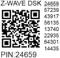
First five digits are highlighted/underlined. DSK is also represented via QR code.
Joining node obfuscates public key by setting bytes 1–2 to zero (0x00) before RF transfer.
DSK may be used for out-of-band (OOB) authentication.
Gateway can scan QR code to match obfuscated public key received via RF.
Z-Wave Parameters
Parameter No. 1 – SW (SW1) Switch Type
- Defines how device treats switch on SW (SW1)
- Size: 1 Byte
- Default: 0
- Values:
- 0: Momentary switch (push button)
- 1: Toggle switch (contact closed = ON / open = OFF)
- 2: Toggle switch (device changes status when switch changes)
Parameter No. 2 – SW2 Switch Type
- Same as above
- Default: 0
Parameter No. 3 – SW3 Switch Type
- Same as above
- Default: 0
Parameter No. 4 – SW4 Switch Type
- Same as above
- Default: 0
Parameter No. 105 – LED Signalisation Intensity
- Controls LED brightness (0–100%)
- Implemented in 2024 for Wave 1, Wave 1PM, Wave 2PM, Plug US, Plug UK
- Size: 1 Byte
- Default: 100
- Values: 0–100 (every 1%)
Parameter No. 120 – Factory Reset
- Advanced parameter (may be hidden)
- Size: 1 Byte
- Default: 0
- Values:
- 0: No action
- 1: Factory reset
- After reset, value automatically sets to 0.
Parameters 201–203 – Serial Number Parts
- Read-only, part of device serial number
- Size: 4 Bytes each
- Default: Device-specific
- Values: 0x00000000 – 0x7FFFFFFF
Z-Wave Command Classes
Root Device (Endpoint 1):
- ASSOCIATION_V2 [S0, S2]
- ASSOCIATION_GRP_INFO_V3 [S0, S2]
- BASIC_V2 [S0, S2]
- SWITCH_BINARY_V2 [S0, S2]
- CENTRAL_SCENE_V3 [S0, S2]
- CONFIGURATION_V4 [S0, S2]
- DEVICE_RESET_LOCALLY_V1 [S0, S2]
- FIRMWARE_UPDATE_MD_V5 [S0, S2]
- INDICATOR_V3 [S0, S2]
- MANUFACTURER_SPECIFIC_V2 [S0, S2]
- MULTI_CHANNEL_V4 [S0, S2]
- MULTI_CHANNEL_ASSOCIATION_V3 [S0, S2]
- SWITCH_MULTILEVEL_V4 [S0, S2]
- NOTIFICATION_V8 [S0, S2]
- POWERLEVEL_V1 [S0, S2]
- SECURITY_V1
- SECURITY_2_V1
- SUPERVISION_V1
- VERSION_V3 [S0, S2]
- ZWAVEPLUS_INFO_V2
Endpoint 2:
- Same as Root Device except no SWITCH_BINARY_V2, etc.
(Similar lists for Endpoints 3, 4, 5)
Z-Wave Notifications Command Class
Overheat Detected
| Field | Value |
|---|---|
| Notification Type Name | Heat Alarm |
| Notification Type (Value) | 0x04 |
| Notification Event | State |
| Notification Name | Overheat detected |
| Notification Name (Value) | 0x02 |
| Version | V2 |
| Device specific | Yes |
| LED signalisation | See LED table |
| Device reaction | Switches off outputs, sends notification |
| Restore action | Power cycle, short S button press |
Z-Wave Associations
Associations enable direct device-to-device communication without gateway involvement.
- Max 9 devices per group (recommended ≤5 per group)
- "Lifeline Group" reserved for gateway (only 1 node allowed)
Root Device – Association Group 1 (Lifeline)
- Reports device status
- Supports:
- INDICATOR_REPORT (LED status)
- DEVICE_RESET_LOCALLY_NOTIFICATION
- SWITCH_BINARY_REPORT (SW1–SW4 status)
Group 4 (SW1 – Basic Command)
- Triggered by SW1
- Sends BASIC_SET ON/OFF to associated devices
Group 5 (SW1 – Multilevel)
- Triggered by SW1
- Recommended for push buttons
- Commands: SWITCH_MULTILEVEL_START_LEVEL_CHANGE, STOP_LEVEL_CHANGE
Groups 6–11 (SW2–SW4)
Same structure as above (Basic + Multilevel commands)
(Full details available in original document)
Z-Wave Important Disclaimer
Z-Wave wireless communication may not always be 100% reliable. Do not rely solely on this device for life-or-value-critical operations. If device isn’t recognized, manually change device type and confirm gateway supports Z-Wave Plus™ multi-level devices.
Troubleshooting
Visit our support portal: https://support.shelly.cloud/
Compatibility with Gateways
| Gateway | D Control 1 | D Control 2 | D Control 3 | D Control 4 | D Binary 1 | D Binary 2 | D Binary 3 | D Binary 4 | Notes |
|---|---|---|---|---|---|---|---|---|---|
| Home Assistant | ✅ | ✅ | ✅ | ✅ | ✅ | ✅ | ✅ | ✅ | |
| Fibaro HC 3 / Z-Wave engine 3 | ✅ | ✅ | ✅ | ✅ | ✅ | ✅ | ✅ | ✅ | |
| Homey | ✅ | ✅ | ✅ | ✅ | ✅ | ✅ | ✅ | ✅ | *H |
| Homee Cube Gen 7 | ✅ | ✅ | ✅ | ✅ | ✅ | ✅ | ✅ | ✅ | |
| Homee Cube Gen 5 | ⚪ | ⚪ | ⚪ | ⚪ | ⚪ | ⚪ | ⚪ | ⚪ | *1 |
| Smart Things | ✅ | ✅ | ✅ | ✅ | With Shelly Wave edge driver | ||||
| Vera Ezlo | ⚪ | ⚪ | ⚪ | ⚪ | ✅ | ✅ | ✅ | ✅ | *2 |
Notes:
- 1: Cannot use Central Scene or Association automation
- 2: Missing CC control scene feature
- H: Issues with reports — see solution
Function Meaning Table
| Function | Meaning / Tested |
|---|---|
| On/Off | Responds to app UI On/Off command |
| SW On/Off | Reports On/Off changes via SW input |
| Dimming | Responds to app UI dimming command |
| SW Dimming | Reports dimming state via SW input |
| Watts | Watts reported unsolicited |
| kWh | kWh reported unsolicited |
| Up/Down | Responds to app UI Up/Down command |
| SW Up/Down | Reports Up/Down changes via SW input |
| Slats | Slats respond to app UI command |
| SW Slats | Slats report changes via SW |
| D control | Reports scene commands (single/double press, etc.) |
| D Binary | Reports binary On/Off via SW input |
| Sensor # | Sensor visible in gateway; note type |
Legend
| Symbol | State |
|---|---|
| ✅ | Working / Possible |
| ⚪ | Not Working / Not Possible |
| P | Partially |
| N/T | Not Tested |
| TBD | To be done |
Gateway Guides
Useful guides available in the Shelly Knowledge Base
Compliance
- Shelly Qubino Wave i4 multilingual EU Declaration of Conformity (240)
- Wave i4 UK PSTI ACT Statement of Compliance