Device Identification
Device: Wave Pro Shutter
- US Part number/Ordering Code: QPSH-0A1P10US
- Z-Wave Product type ID: 0x0003
- Z-Wave Product ID: 0x0084
- Z-Wave Manufacturer: Shelly Europe Ltd.
- Z-Wave Manufacturer ID: 0x0460
Terminology
- Device – In this document, the term “Device” refers to the Shelly Qubino device that is the subject of this guide.
- Gateway (GW) – A Z-Wave™ gateway, also referred to as a Z-Wave™ controller, Z-Wave™ main controller, Z-Wave™ primary controller, or Z-Wave™ hub, etc., is a device that serves as a central hub for a Z-Wave™ smart home network. The term “gateway” is used in this document.
- S button – The Z-Wave™ Service button, located on Z-Wave™ devices and used for various functions such as adding (inclusion), removing (exclusion), and resetting the device to its factory default settings. The term “S button” is used in this document.
- Adding/Inclusion – The process of adding a Z-Wave device to a Z-Wave network (gateway). Words like included, added, etc., are used in this context.
- Removing/Exclusion – The process of removing a Z-Wave device from a Z-Wave network (gateway). Words like excluded, removed, etc., are used in this context.
Short Description
[Error: User '712020:515aa595-e304-41f3-886a-d9b6b0b7f5a3' does not have permission to view the page 'DEV:About the Device'.]
Manual Operation for Shutter
Manual Operation with Momentary Switch
- Parameter No. 71 set to
0 - Parameter No. 1 set to
0
Actions:
- Pressing the push-button connected to SW1 (up) for less than 0.5 seconds (short press) initiates upward movement.
- Pressing the push-button connected to SW2 (down) for less than 0.5 seconds (short press) initiates downward movement.
- If the shutter is moving, any press (on any push-button) will stop the movement.
- Pressing SW1 for more than 0.5 seconds (long press) starts upward movement until the button is released.
- Pressing SW2 for more than 0.5 seconds (long press) starts downward movement until the button is released.
Action Table:
| Action on Push-Button | Blind Not Moving | Blind Moving Up | Blind Moving Down | Tilting Slats Ongoing |
|---|---|---|---|---|
| Short press (UP) | Start moving up | Stop moving | Stop moving | No action |
| Short press (DOWN) | Start moving down | Stop moving | Stop moving | No action |
| Long press (UP) | Start moving up (incl. slat tilt for venetian) | Moving | Moving | Tilting to end → move UP |
| Long press (DOWN) | Start moving down (incl. slat tilt for venetian) | Moving | Moving | Tilting to end → move DOWN |
| Release after long press | No action | Stop moving | Stop moving | Stop tilting |
Manual Operation with Toggle Switch
Parameter No. 71 set to
0Parameter No. 1 set to
1Pressing the toggle switch connected to SW1 (up) initiates upward movement until released.
Pressing the toggle switch connected to SW2 (down) initiates downward movement until released.
Manual Operation for Venetian Blinds with Momentary Switch
- Parameter No. 71 set to
1 - Parameter No. 1 set to
0
General Rules:
- Short press (< 0.5 s): initiates blind movement
- Long press (> 0.5 s): initiates slats rotation
Actions:
- Short press (SW1 UP): start moving up
- Short press (SW2 DOWN): start moving down
- Long press (SW1 UP): initiate slats rotation (0% → 100%), time defined by Parameter No. 72
- Long press (SW2 DOWN): initiate slats rotation (100% → 0%), time defined by Parameter No. 72
Action Table:
| Action on Push Button | Blind Not Moving | Blind Moving Up | Blind Moving Down | Tilting Slats Ongoing |
|---|---|---|---|---|
| Short press (UP) | Start moving up | Stop moving | Stop moving | Stop tilting |
| Short press (DOWN) | Start moving down | Stop moving | Stop moving | Stop tilting |
| Long press (UP) | Start tilting slats | No action | No action | Continue tilting |
| Long press (DOWN) | Start tilting slats | No action | No action | Continue tilting |
| Release after long press | No action | Stop moving | Stop moving | Stop tilting |
Manual Operation for Venetian Blinds with Toggle Switch
Parameter No. 71 set to
1Parameter No. 1 set to
1Pressing a toggle switch on SW1 (up) starts upward movement until released.
Pressing a toggle switch on SW2 (down) starts downward movement until released.
When slats are at 100%, quick press of UP moves blind up.
When slats are at 0%, quick press of DOWN moves blind down.
Slats Positioning
To achieve maximum precision when stopping via button, gateway, or remote control:
- When slats are in an intermediate position and receive a new command, they first rotate to 100%, then back to the target position.
- When moving down and limit switch is reached (or stopped), slats rotate to 100% then return to previous position.
- When moving up and stopped, slats rotate back to the previous position.
Main Applications
- Residential
- MDU (Multi Dwelling Units – apartments, condominiums, hotels, etc.)
- Light commercial (small office buildings, retail/restaurant/gas stations, etc.)
- Government/municipal
- University/college
- Farming
Integrations
Shelly Qubino Wave devices are built on Z-Wave, the world’s leading smart home technology. This means they work with all certified gateways supporting the Z-Wave protocol.
We regularly test compatibility across different Z-Wave gateways to ensure full functionality.
Simplified Internal Schematics
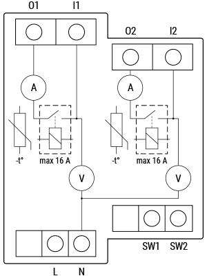
Device Electrical Interfaces
Inputs
- 2 switch/button inputs on screw terminals
- 2 power supply inputs on screw terminals: N and L
Outputs
- 2 relay outputs with power measurement on screw terminals
Connectivity
- Z-Wave: Unsecure, S0 Security, S2 Unauthenticated Security, S2 Authenticated Security
Safety Features
- Over-load detection
- Overheat detection
Supported Load Types
[Error: User '712020:515aa595-e304-41f3-886a-d9b6b0b7f5a3' does not have permission to view the page 'DEV:Supported load types'.]
User Interface
S Button and Operating Modes
- Normal mode
- Setting in progress mode
- Setting mode (with S button)
- Required to perform actions like inclusion, exclusion, or factory reset.
- Limited-time operation; auto-returns to Normal mode after completion.
- Entering Setting Mode:
- Quickly press and hold the S button until the LED turns solid blue.
- An additional quick press changes the menu (infinite loop).
- Menu timeout: 10 seconds before returning to Normal state.
S Button Functions
- Manually add device to Z-Wave network
- Manually remove device from Z-Wave network
- Factory reset device
Functionality
Automatic Calibration
The device learns the position of the limit switches during calibration.
Note! For correct operation, calibration must be performed!
Note! The motor must have electronic or mechanical limit switches properly set before calibration.
Shutter Positioning Calibration (Shutter Mode)
- Parameter No. 71 =
0
Calibration with Gateway
- Add the device to the Z-Wave network (inclusion).
- Set Parameter No. 78 (forced Shutter calibration) to
1. - Device performs full cycle: up → down → up → down to 50%.
- Check Parameter No. 78: value
2= success,3or4= error. - Yellow LED should not blink.
If values 3 or 4: Verify full cycle execution, correct limit switch settings, and proper wiring.
Calibration with Push-Button (SW1)
- Move blind to top position.
- Press SW1 four times within 3 seconds.
- Device starts calibration (4 cycles: up, down, up, down to 50%).
- No time limit.
Calibration with S Button
- Enter Setting mode (short press S button).
- Hold S button until yellow LED appears (calibration selected).
- Press S button for >2 seconds to start calibration.
- Confirm yellow LED is stable (no blinking).
If yellow LED blinks: Check full cycle, limit switches, and wiring.
Slats Tilting Position Calibration (Venetian Mode)
- Parameter No. 71 =
1
After enabling venetian blind mode, calibrate slats positioning.
- Default rotation time: 1.5 seconds (adjustable via Parameter No. 72).
Steps:
- Add and calibrate using the "Shutter positioning calibration" procedure.
- Set Parameter No. 71 to
1("Venetian blinds"). - Adjust Parameter No. 72:
- Too short? Increase time.
- Too long? Decrease time (if blind starts moving during slat rotation).
- Repeat until slats position is accurate.
Note: Correct timing prevents unwanted blind movement during slat adjustment.
LED Signalisation
General Rules
- Press S button once to toggle between Normal and Setting modes.
- Solid LED = Setting mode (except plugs). Auto-returns to Normal after 10s.
- LED turns off after 30 min (unless woken by S button or power cycle).
Normal Mode LED Status
| Condition | LED Behavior |
|---|---|
| Removed/Excluded / Not Calibrated | Blinking blue (10 min after power-on or S button press) |
| Removed/Excluded / Calibrated | Blinking blue & yellow (30 min after power-on, 10 min after S button press) |
| Added/Included / Not Calibrated | Blinking green (10 min after power-on or S button press) |
| Added/Included / Calibrated | Blinking green & yellow (30 min after power-on, 10 min after S button press) |
Settings in Progress
| Event | LED Behavior |
|---|---|
| Factory Reset & Reboot | Solid green (1 sec), then blue & red blinking (0.1s on/off, ~2 sec) |
| Adding/Removing | Blinking blue (Mode 2) |
| Shutter Calibration | Blinking yellow (Mode 2) |
Settings Mode with S Button
| Menu Selected | LED Behavior |
|---|---|
| Adding/Removing | Solid blue (max 10s) |
| Adding/Removing (during) | Blinking blue (Mode 3) |
| Factory Reset | Solid red (max 10s) |
| Factory Reset (during) | Blinking red (Mode 3) |
| Calibration | Solid yellow (max 10s) |
| Calibration (during) | Blinking yellow (Mode 3) |
Alarm Mode
| Alarm Type | LED Behavior |
|---|---|
| Over-current detected | Red blinking: 1x (0.2s on/off), 2s off → repeat |
| Overheat detected | Red blinking: 2x (0.2s on/off), 2s off → repeat |
| Power Supply Fault | Red blinking: 3x (0.2s on/off), 2s off → repeat |
LED Blinking Modes
| Mode | Blink Pattern |
|---|---|
| 1 | 0.5s On / 2s Off |
| 2 | 0.5s On / 0.5s Off |
| 3 | 0.1s On / 0.1s Off |
| 4 | (1–6x: 0.2s On/Off) + 2s Off |
| 5 | 0.2s Blue On / 0.2s Red On |
Specifications
[Error: User '712020:515aa595-e304-41f3-886a-d9b6b0b7f5a3' does not have permission to view the page 'DEV:Technical Specifications'.]
Basic Wiring Diagram
[Error: User '712020:515aa595-e304-41f3-886a-d9b6b0b7f5a3' does not have permission to view the page 'DEV:Wiring diagrams'.]
Legend
Unable to render {include} – The included page could not be found.
About Z-Wave
Adding the Device to a Z-Wave® Network (Inclusion)
Note! The blind will move 2s up/down if the device is successfully added/removed.
Note! For S2 inclusion, enter the 5-digit PIN from the DSK label on the device or packaging.
IMPORTANT: Never lose the PIN.
SmartStart Inclusion
- Scan the Z-Wave QR code on the device with a SmartStart-enabled gateway.
- Connect device to power.
- If blue LED blinks slowly → not added.
- Addition starts automatically within seconds.
- Blue LED blinks faster during inclusion.
- Green LED blinks slowly upon successful addition.
Adding with S Button
- Connect device to power.
- Check if blue LED blinks slowly.
- Enable add/remove mode on gateway.
- Press and hold S button until LED turns solid blue.
- Release, then press and hold (>2s) until blue LED blinks slowly → release to start learn mode.
- Blue LED blinks faster during inclusion.
- Green LED blinks slowly if successful.
Note: Setting mode times out after 10s.
Adding with Switch/Push-Button
- Connect device to power.
- Check if blue LED blinks slowly.
- Enable add/remove mode on gateway.
- Toggle switch/push-button 3 times within 3 seconds (must receive 3 on/off signals).
- Blue LED blinks faster during inclusion.
- Green LED blinks slowly if successful.
Learn Mode: State allowing device to receive network info from gateway.
Removing the Device from a Z-Wave® Network (Exclusion)
Note! Custom parameters remain unchanged after removal.
Note! Blind moves 2s up/down upon successful removal.
Removing with S Button
- Connect device to power.
- Check if green LED blinks slowly (device is added).
- Enable add/remove mode on gateway.
- Press and hold S button until LED turns solid blue.
- Release, then press and hold (>2s) until blue LED blinks slowly → release to start learn mode.
- Blue LED blinks faster during removal.
- Blue LED blinks slower if successful.
Removing with Switch/Push-Button
- Connect device to power.
- Check if green LED blinks slowly.
- Enable add/remove mode on gateway.
- Toggle switch/push-button 3 times within 3 seconds.
- Blue LED blinks faster during removal.
- Blue LED blinks slower if successful.
Factory Reset
General
- Resets all custom parameters, kWh, associations, routing, HOME ID, NODE ID.
- Use only if gateway is missing/inoperable.
With S Button
- Press and hold S button until LED turns solid blue.
- Press S button multiple times until LED turns solid red.
- Hold S button (>2s) until red LED blinks fast → release to start reset.
- During reset: green (1s), then blue & red blink fast (~2s).
- Blue LED blinks slowly if successful.
With Switch/Push-Button
Only possible within first minute after power-up.
- Connect device to power.
- Toggle switch/push-button 5 times within 3 seconds.
- During reset: green (1s), then blue & red blink fast (~2s).
- Blue LED blinks slowly if successful.
Z-Wave Security and Device Specific Key (DSK)
The device supports Security 2 (S2) with AES-128 encryption — the most secure IoT platform available.
- Supports S2 Authenticated, Unauthenticated, and Unsecure inclusion.
- For S2 inclusion, the DSK PIN (first five digits of DSK label) is required.
- DSK label is on the side of the device and inside the packaging.
- Do not remove the label.
QR Code Example:
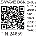
- First 5 digits highlighted/underlined → PIN code.
- DSK may be used for out-of-band (OOB) authentication.
Z-Wave Parameters
[Error: Unable to render {include} – The included page could not be found.]
Z-Wave Command Class
[Error: Unable to render {include} – The included page could not be found.]
Z-Wave Notifications Command Class
[Error: Unable to render {include} – The included page could not be found.]
Z-Wave Associations
[Error: Unable to render {include} – The included page could not be found.]
Z-Wave Important Disclaimer
Z-Wave wireless communication may not always be 100% reliable. This device should not be used where life or valuable assets depend solely on its function. If unrecognized by your gateway, manually change device type and verify support for Z-Wave Plus™ multi-channel devices.
Troubleshooting
For help, visit our support portal: https://support.shelly.cloud/
Compatibility with Gateways
| Gateway | Up | Down | SW Up | SW Down | W | kWh | Slats | SW Slats | Notes |
|---|---|---|---|---|---|---|---|---|---|
| Home Assistant | ✅ | ✅ | ✅ | ✅ | ✅ | ✅ | ✅ | ✅ | |
| Fibaro HC 3 / Z-Wave engine 3 | ✅ | ✅ | ✅ | ✅ | ❌ | ❌ | ✅ | ✅ | |
| Homey | ✅ | ✅ | ✅ | ✅ | ❌ | ❌ | ✅ | ✅ | |
| Homee Cube Gen 7 | ✅ | ✅ | ✅ | ✅ | ✅ | ✅ | ⚪ | ⚪ | *1 |
| Homee Cube Gen 5 | ✅ | ✅ | ⚪ | ⚪ | ⚪ | ⚪ | ⚪ | ⚪ | *1, *2, *3 |
| Smart Things | TBD | TBD | TBD | TBD | TBD | TBD | TBD | TBD | With Shelly Wave edge driver |
| Vera Ezlo | ✅ | ✅ | ✅ | ✅ | ✅ | ✅ | ✅ | ✅ | |
| Cozify | ✅ | ✅ | ✅ | ✅ | ✅ | ✅ | ✅ | ✅ |
Notes:
*1: Slats cannot be controlled via UI; position not visualized.
*2: UI reports sent only via buttons; slider sends to location but doesn’t refresh state.
*3: State refreshes only after stop button pressed.
*4: Device goes to position but state not reported.
Legend
| Symbol | Meaning |
|---|---|
| ✅ | Working / Possible |
| ⚪ | Not Working / Not Possible |
| P | Partially |
| N/T | Not Tested |
| TBD | To be done |
Function Definitions
| Function | Meaning / Tested |
|---|---|
| On/Off | Responds to app UI On/Off command |
| SW On/Off | Reports On/Off changes via SW input |
| Dimming | Responds to app UI dimming command |
| SW Dimming | Reports dimming state change via SW input |
| Watts | Reports watts (unsolicited) |
| kWh | Reports kWh (unsolicited) |
| Up/Down | Responds to app UI Up/Down command |
| SW Up/Down | Reports Up/Down changes via SW input |
| Slats | Slats respond to app UI command |
| SW Slats | Slats report changes made via SW |
| D control | Detached mode: reports scene commands (single/double press, etc.) |
| D Binary | Detached mode: reports binary On/Off via SW input |
| Sensor # | Sensor report visible in gateway; type noted |
Gateway Guides
Useful guides: Shelly Knowledge Base – Z-Wave
Compliance
- Wave Pro Shutter multilingual EU Declaration of Conformity (2025-07-23)
- Wave Pro Shutter UK PSTI ACT Statement of Compliance