Shelly Wave 1 - Device Documentation
Note: The product line known as "Shelly Qubino Wave" will now be referred to as "Shelly Wave". This name change will not impact the functionality of any devices. The only modification will be the use of the new name in all future documentation.
Device Identification
- Device name: Wave 1
- AUS Part number / Ordering Code: QNSW-001X16AU
- Z-Wave Product type ID: 0x0002
- Z-Wave Product ID: 0x0083
- Z-Wave Manufacturer: Shelly Europe Ltd.
- Z-Wave Manufacturer ID: 0x0460
Terminology
- Device: In this document, the term “Device” refers to the Shelly Qubino device that is the subject of this guide.
- Gateway: A Z-Wave® gateway (also referred to as a Z-Wave® controller, Z-Wave® main controller, Z-Wave® primary controller, or Z-Wave® hub) acts as a central hub for a Z-Wave® smart home network. The term “gateway” is used throughout this document.
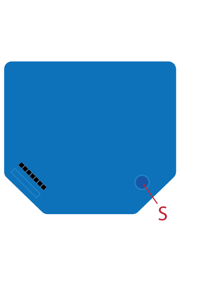
- S button: The Z-Wave® Service button, located on Z-Wave® devices, is used for functions such as adding (inclusion), removing (exclusion), and resetting the device to factory defaults. The term “S button” is used in this document.
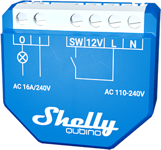
Short Description
The Device controls the on/off function for one electrical device (e.g., bulb, ceiling fan, IR heater, electric locks, garage doors, irrigation systems, etc.). The output contact is potential-free (dry contact), allowing different power supply loads (up to 16 A) to be connected. It is compatible with push-buttons and switches by default.
Switch Connected to Input Terminal SW (SW1)
If the SW (SW1) is configured as a switch (default):
- Each toggle of the switch changes the output state O (O1) to the opposite state — ON, OFF, ON, etc.
Actions:
- Change switch position once: Toggle the output state O (O1) to the opposite and send command to associated devices in groups 2 and 3 (see Z-Wave Associations).
- Change switch position twice: If the delay between the first and second click is less than 500ms, it's interpreted as a double press. Send command to associated dimmers, shutters, etc., in groups 2 and 3.
Main Applications
- Residential
- MDU (Multi Dwelling Units – apartments, condominiums, hotels, etc.)
- Light commercial (small office buildings, retail, restaurants, gas stations, etc.)
- Government / Municipal
- University / College
Integrations
Shelly Qubino Wave devices are built on the world’s leading smart home technology – Z-Wave.
This means they work with all certified gateways supporting the Z-Wave communication protocol.
To ensure full functionality, we regularly test compatibility with various Z-Wave gateways.
Simplified Internal Schematics
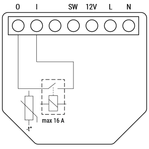
Device Electrical Interfaces
Inputs
- 1 switch/button input on screw terminal
- 1 potential-free contact relay input on screw terminal
- 2 power supply inputs on screw terminals: N and L
Outputs
- 1 potential-free contact relay output on screw terminal
Connectivity
Z-Wave – Unsecure, S0 Security, S2 Unauthenticated Security, S2 Authenticated Security
Safety Features
Overheat Protection
- Automatically switches off its own relay
- Sends a Notification Report to the Gateway ("Overheat detected")
- LED reacts according to specified blinking mode (check "LED Signalisation")
Any of the following actions reset the alarm:
- Power cycle
- Short press on S button
- Press any switch/push-button connected to any SW (SW, SW1, SW2, ...) terminal
NOTE: Overheat protection is always active and cannot be disabled.
Additional details: See Z-Wave Notifications Command Class
Supported Load Types
- Resistive (incandescent bulbs, heating devices)
- Capacitive (capacitor banks, electronic equipment, motor start capacitors)
- Inductive with RC Snubber (LED light drivers, transformers, fans, refrigerators, air conditioners)
User Interface
S Button and Operating Modes
- Normal Mode
- Setting in Progress Mode
- Setting Mode (with S button)
- Required to initiate procedures like inclusion, exclusion, factory reset
- Limited time; automatically returns to Normal Mode after completion
- Entering Setting Mode:
- Quickly press and hold the S button until the LED turns solid blue
- An additional quick press cycles through menus (infinite loop)
- Menu LED status times out after 10 seconds before returning to Normal State
S Button Functions
- Manually add the Device to a Z-Wave network
- Manually remove the Device from a Z-Wave network
- Factory Reset the Device
- Manually switch the load On/Off
LED Signalisation
Normal Mode
- Removed/Excluded: LED blinks blue in Mode 1 for 10 minutes after power cycle or S button press

- Added/Included: LED blinks green in Mode 1 for 10 minutes after power cycle or S button press

Settings in Progress
- Factory Reset & Reboot:
- Solid green for ~1 sec → blue and red blink rapidly (0.1s on/off) for ~2 sec
- Adding / Removing: LED blinks blue in Mode 2

- Firmware OTA Update: LED blinks blue and red in Mode 2

- Power Supply Check (230V AC / 24V DC): LED blinks blue and red in Mode 5

Settings Mode with S Button
- Menu Selected (Add/Remove): LED stays blue for up to 10 seconds
- During Add/Remove Process: LED blinks blue in Mode 3

- Menu Selected (Factory Reset): LED stays red for up to 10 seconds
- During Factory Reset Process: LED blinks red in Mode 3

Alarm Mode
- Overheat Detected: LED blinks red in Mode 4 — pattern: (1–6 times: 0.2s On / 0.2s Off) + 2s Off

LED Blinking Modes
| Mode | Description |
|---|---|
| Mode 1 | 0.5s On / 2s Off |
| Mode 2 | 0.5s On / 0.5s Off |
| Mode 3 | 0.1s On / 0.1s Off |
| Mode 4 | (1–6 x 0.2s On / 0.2s Off) + 2s Off |
| Mode 5 | 0.2s On (blue) / 0.2s On (red) |
Specifications
| Parameter | Value |
|---|---|
| Power Supply | 110–240 V AC, 50/60 Hz |
| Power Consumption | < 0.3 W |
| Max. Switching Voltage AC | 240 V |
| Max. Switching Current AC | 16 A |
| Overheating Protection | Yes |
| Communication Range | Up to 40 m indoors (131 ft) – depends on local conditions |
| Z-Wave® Repeater | Yes |
| CPU | Z-Wave® S800 |
| Z-Wave® Frequency Bands | 919.8 MHz |
| Max. Radio Frequency Power | < 25 mW |
| Dimensions (H × W × D) | 37 × 42 × 16 ±0.5 mm / 1.46 × 1.65 × 0.63 ±0.02 in |
| Weight | 26 g / 0.92 oz. |
| Mounting | Wall console |
| Screw Terminal Torque | 0.4 Nm / 3.5 lbin |
| Conductor Cross Section | 0.5 to 1.5 mm² / 20 to 16 AWG |
| Conductor Stripped Length | 5 to 6 mm / 0.20 to 0.24 in |
| Shell Material | Plastic |
| Color | Blue |
| Ambient Temperature | -20°C to 40°C / -5°F to 105°F |
| Humidity | 30% to 70% RH |
| Max. Altitude | 2000 m / 6562 ft |
Basic Wiring Diagram
| Diagram 1 | Diagram 2 |
|---|---|
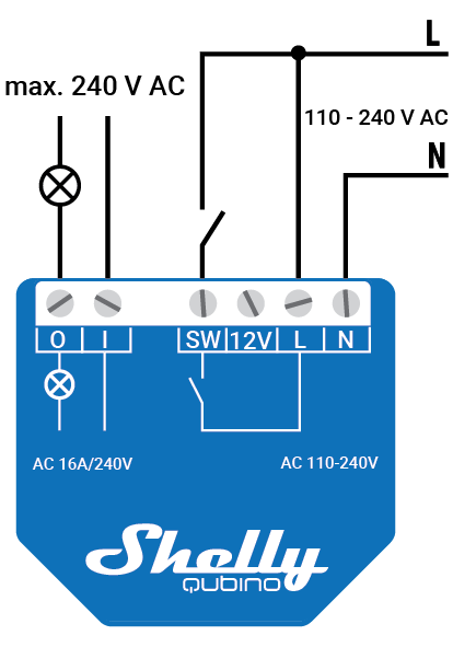 |  |
Legend
| Terminal | Description | Cable | Description |
|---|---|---|---|
| N | Neutral terminal | N | Neutral wire |
| L | Live terminal (110–240 V AC) | L | Live (110–240 VAC) wire |
| SW | Switch/push-button input terminal (controls O) | — | — |
| I | Load circuit input terminal | — | — |
| O | Load circuit output terminal | — | — |
About Z-Wave®
Adding the Device to a Z-Wave® Network (Inclusion)
Note! All device outputs (O, O1, etc.) will briefly turn on/off 1 second each if the device is successfully added/removed.
Important: For Security 2 (S2) inclusion, enter the 5-digit PIN code found on the Z-Wave® DSK label (on device and packaging). Do not lose this code.
SmartStart Inclusion
- Scan the Z-Wave® QR code on the device using a gateway with SmartStart support.
- Connect the device to power.
- Confirm the blue LED is blinking in Mode 1 (not added).
- The device auto-includes within seconds.
- Blue LED blinks in Mode 2 during inclusion.
- Green LED blinks in Mode 1 upon successful addition.
Adding with S Button
- Connect device to power.
- Ensure blue LED blinks in Mode 1.
- Enable add/remove mode on the gateway.
- Press and hold S button until LED turns solid blue.
- Release, then press and hold (>2s) until LED blinks in Mode 3 → releases to start Learn mode.
- Blue LED blinks in Mode 2 during inclusion.
- Green LED blinks in Mode 1 upon success.
Note: Setting mode times out after 10 seconds.
Adding with Switch/Push-Button
- Connect device to power.
- Confirm blue LED in Mode 1.
- Enable add/remove mode on gateway.
- Toggle the switch/push-button on any SW terminal 3 times within 3 seconds (must receive 3 on/off signals).
- Blue LED blinks in Mode 2 during inclusion.
- Green LED blinks in Mode 1 upon success.
Learn Mode: State enabling device to receive network info from gateway.
Removing the Device from a Z-Wave® Network (Exclusion)
Note: The device is removed from the network, but custom configurations are retained.
Removing with S Button
- Connect device to power.
- Confirm green LED blinks in Mode 1 (added).
- Enable add/remove mode on gateway.
- Press and hold S button until LED turns solid blue.
- Release, then press and hold (>2s) until LED blinks in Mode 3 → starts Learn mode.
- Blue LED blinks in Mode 2 during removal.
- Blue LED blinks in Mode 1 upon success.
Note: Setting mode times out after 10 seconds.
Removing with Switch/Push-Button
- Connect device to power.
- Confirm green LED in Mode 1.
- Enable add/remove mode on gateway.
- Toggle switch/push-button on any SW terminal 3 times within 3 seconds.
- Blue LED blinks in Mode 2 during removal.
- Blue LED blinks in Mode 1 upon success.
Factory Reset
General
After reset, all custom settings, associations, kWh data, routing, etc., revert to defaults. HOME ID and NODE ID are deleted. Use only when gateway is missing or inoperable.
With S Button
- Press and hold S button until LED turns solid blue.
- Press S button repeatedly until LED turns solid red.
- Hold S button (>2s) until red LED blinks in Mode 3 → starts reset.
- LED turns solid green (~1s), then blue/red blink rapidly (~2s).
- Blue LED blinks in Mode 1 if successful.
With Switch/Push-Button
Only possible within first minute after power-up
- Connect device to power.
- Toggle switch/push-button on any SW terminal 5 times within 3 seconds.
- LED turns solid green (~1s), then blue/red blink rapidly (~2s).
- Blue LED blinks in Mode 1 if successful.
Remote Factory Reset via Gateway
Use Parameter No. 120 to trigger remote factory reset.
Z-Wave® Security and Device Specific Key (DSK)
The device supports Security 2 (S2) using Strong AES-128 encryption — making Z-Wave® the most secure IoT platform available.
- Supports: S2 Authenticated, S2 Unauthenticated, and Unsecure inclusion
- Requires S2-enabled gateway
Note: During S2 inclusion, you must provide the 5-digit PIN from the DSK label (on device and packaging). Keep the label intact.
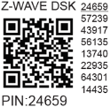
- First five digits are highlighted/underlined (PIN code)
- DSK also represented via QR code
Out-of-Band (OOB) Authentication
- Including gateway reads entire DSK via QR scan
- Matches obfuscated public key received over RF
- Joining node sets bytes 1–2 to
0x00before sending key
Z-Wave® Parameters
| Parameter No. | Description | Size | Default | Values & Descriptions |
|---|---|---|---|---|
| 1 | SW (SW1) Switch Type | 1 Byte | 2 | 0 = momentary 1 = toggle (closed=ON) 2 = toggle (state changes on switch change) |
| 17 | Restore O (O1) After Power Failure | 1 Byte | 0 | 0 = restore last state 1 = remain OFF after failure |
| 19 | O (O1) Auto OFF Timer | 2 Bytes | 0 | 0 = Disabled 1–32535 = seconds (or ms if Param 25 = 1) |
| 20 | O (O1) Auto ON Timer | 2 Bytes | 0 | 0 = Disabled 1–32535 = seconds (or ms if Param 25 = 1) |
| 23 | O (O1) Contact Type (NO/NC) | 1 Byte | 0 | 0 = NO (normally open) 1 = NC (normally closed) |
| 25 | Timer Unit (s or ms) | 1 Byte | 0 | 0 = seconds 1 = milliseconds |
| 91 | Water Alarm Response | 4 Bytes | 0 | 0 = no action 1 = open relay 2 = close relay |
| 92 | Smoke Alarm Response | 4 Bytes | 0 | 0 = no action 1 = open relay 2 = close relay |
| 93 | CO Alarm Response | 4 Bytes | 0 | 0 = no action 1 = open relay 2 = close relay |
| 94 | Heat Alarm Response | 4 Bytes | 0 | 0 = no action 1 = open relay 2 = close relay |
| 120 | Factory Reset (Remote) | 1 Byte | 0 | 0 = don’t reset 1 = reset to factory |
| 201–203 | Serial Number (Parts 1–3) | 4 Bytes | Device-specific | Read-only; hidden under Advanced tag |
Relay Logic Table (for Parameter 23):
| NO/NC | Command | Output State |
|---|---|---|
| NO (0) | OFF | 0 V |
| NO (0) | ON | 230 V |
| NC (1) | OFF | 230 V |
| NC (1) | ON | 0 V |
Z-Wave® Command Classes
- ASSOCIATION_V2 [S0, S2]*
- ASSOCIATION_GRP_INFO_V3 [S0, S2]*
- BASIC_V2 [S0, S2]*
- SWITCH_BINARY_V2 [S0, S2]*
- CONFIGURATION_V4 [S0, S2]*
- DEVICE_RESET_LOCALLY_V1 [S0, S2]*
- FIRMWARE_UPDATE_MD_V5 [S0, S2]*
- INDICATOR_V3 [S0, S2]*
- MANUFACTURER_SPECIFIC_V2 [S0, S2]*
- MULTI_CHANNEL_ASSOCIATION_V3 [S0, S2]*
- NOTIFICATION_V8 [S0, S2]*
- POWERLEVEL_V1 [S0, S2]*
- SECURITY_V1
- SECURITY_2_V1
- SUPERVISION_V1
- TRANSPORT_SERVICE_V2
- VERSION_V3 [S0, S2]*
- ZWAVEPLUS_INFO_V2
Supported in S0/S2 modes
Z-Wave® Notifications Command Class
| Field | Value |
|---|---|
| Comment | Overheat Detected |
| Notification Type Name | Heat Alarm |
| Notification Type Value | 0x04 |
| Notification Event | State |
| Notification Name | Overheat Detected |
| Notification Name Value | 0x02 |
| Notification Version | V2 |
| Device Specific | Yes |
| LED Signalisation | Refer to LED table |
| Device Reaction | Switch OFF all outputs + send notification |
| Restore Action | Power cycle, short S button press, or switch press |
Z-Wave® Associations
Association Group 1 – Lifeline Group
- Reserved for gateway only (1 node max)
- Reports device status
- Supports:
INDICATOR_REPORT: LED statusDEVICE_RESET_LOCALLY_NOTIFICATION: triggered on requestSWITCH_BINARY_REPORT: output O (O1) status changeNOTIFICATION_REPORT: triggered on Overheat
Association Group 2
- Max 9 nodes
- Triggers on SW (SW1) input
- Uses
BASIC_SETcommand (ON/OFF) - Sends
BASIC_SET ONorOFFto associated devices
Association Group 3
- Max 9 nodes
- Triggers on SW (SW1) input
- Uses
SWITCH_MULTILEVEL_START_LEVEL_CHANGEandSTOP_LEVEL_CHANGE - Sends level change commands to associated devices
⚠️ Recommendation: Limit to ≤5 devices per group to avoid network delays.
Z-Wave® Important Disclaimer
Z-Wave® wireless communication may not always be 100% reliable. Do not rely solely on this device for life-critical or high-value applications. If the device isn't recognized or behaves incorrectly, manually change the device type and verify gateway compatibility with Z-Wave Plus™ multi-level devices.
Troubleshooting
For assistance, visit: Support Portal
Compatibility
| Gateway | On/Off | SW On/Off | Notes |
|---|---|---|---|
| Home Assistant | ✅ | ✅ | |
| Fibaro HC 3 / Z-Wave Engine 3 | ✅ | ✅ | |
| Homey | ✅ | ✅ | |
| Homee Cube Gen 7 | ✅ | ✅ | |
| Homee Cube Gen 5 | ✅ | ✅ | |
| SmartThings | ✅ | ✅ | With Shelly Wave edge driver |
| Vera Ezlo | ✅ | ✅ | |
| Cozify | ✅ | ✅ | |
| Hubitat | ✅ | ✅ |
Legend:
- ✅ = Working / Possible
- ❌ = Not Working / Not Possible
- P = Partially
- N/T = Not Tested
- TBD = To Be Done
Function Meaning
| Function | Meaning / Tested |
|---|---|
| On/Off | Responds to app UI On/Off command |
| SW On/Off | Reports On/Off changes via SW input |
| Dimming | Responds to app UI dimming command |
| SW Dimming | Reports dimming state change via SW |
| Watts | Reports watts unsolicited |
| kWh | Reports kWh unsolicited |
| Up/Down | Responds to app UI Up/Down command |
| SW Up/Down | Reports Up/Down changes via SW |
| Slats | Slats respond to app UI command |
| SW Slats | Slats report changes done by SW |
| D control | Reports scene commands (single/double press) in detached mode |
| D Binary | Reports binary On/Off via SW input in detached mode |
| Sensor # | Sensor reported in gateway; note type |
Gateway Guides
Useful guides: Shelly Knowledge Base – Z-Wave