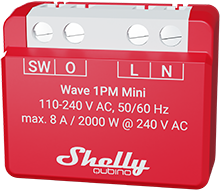
Shelly Wave 1PM Mini
Note: The product line known as "Shelly Qubino Wave" will now be referred to as "Shelly Wave". This name change will not impact the functionality of any devices. The only modification will be the use of the new name in all future documentation.
Device Identification
- Device name: Shelly Wave 1PM Mini
- AUS Part number / Ordering Code: QMSW-0A1P8AU
- Z-Wave Product type ID: 0x0002
- Z-Wave Product ID: 0x008F
- Z-Wave Manufacturer: Shelly Europe Ltd.
- Z-Wave Manufacturer ID: 0x0460
Terminology
- Device: In this document, the term “Device” refers to the Shelly Qubino device that is the subject of this guide.
- Gateway: A Z-Wave® gateway, also referred to as a Z-Wave® controller, Z-Wave® main controller, Z-Wave® primary controller, or Z-Wave® hub, etc., is a device that serves as a central hub for a Z-Wave® smart home network. The term “gateway” is used in this document.
- S button: The Z-Wave® Service button, located on Z-Wave® devices and used for various functions such as adding (inclusion), removing (exclusion), and resetting the device to its factory default settings. The term "S button" is used in this document.
Short Description
The Shelly Wave 1PM Mini is a compact smart switch with power measurement. It controls the on/off function for one electrical appliance with a load of up to 8 A AC, such as a bulb, ceiling fan, or IR heater. It is compatible with switches (default) and push-buttons.
Switch / Push-Button Connected to Input Terminal SW (SW1)
Switch Connected to Input Terminal SW (SW1)
If the SW (SW1) is configured as a switch (default), each toggle of the switch changes the output O (O1) state to the opposite state — on, off, on, etc.
- Change switch position once: Change the state of the output O (O1) to the opposite state and send the command to associated devices in groups 2 and 3 (see Z-Wave Association).
Switch-Memory Connected to Input Terminal SW (SW1)
If the SW (SW1) is configured as a switch-memory:
- Switching to Close switch-memory contact: Change the output state O (O1) to On and send a command to associated devices in groups 2 and 3.
- Switching to Open switch-memory contact: Change the output state O (O1) to Off and send a command to associated devices in groups 2 and 3.
Push-Button Connected to Input Terminal SW (SW1)
If the SW (SW1) is configured as a push-button in the device settings, each press changes the output state O (O1) to the opposite — ON, OFF, ON, etc.
- 1x click: Change the state of O (O1) to the opposite and send a command to associated devices in groups 2 and 3.
- 2x click: If the delay between the first and second click is less than 500ms, it’s interpreted as a double click. Send a command to associated devices (dimmers, shutters, etc.) in groups 2 and 3.
- Hold: Send a command to associated devices in group 3.
- Release: Send a command to associated devices in group 3.
Main Applications
- Residential
- MDU (Multi Dwelling Units – apartments, condominiums, hotels, etc.)
- Light commercial (small office buildings, small retail/restaurant/gas station, etc.)
- Government/municipal
- University/college
Integrations
Shelly Qubino Wave devices are developed using Z-Wave, the world's leading technology for smart homes. This means Shelly Qubino Wave works with all certified gateways supporting the Z-Wave communication protocol.
To ensure full functionality, we regularly perform compatibility tests with various Z-Wave gateways.
Simplified Internal Schematics
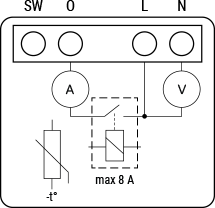
Device Electrical Interfaces
Inputs
- 1 switch/button input on screw terminal
- 2 power supply inputs on screw terminals: N, L
Outputs
- 1 relay output with power measurement on screw terminal
Addon Interface
- N/A
Connectivity
Z-Wave: Unsecure, S0 Security, S2 Unauthenticated Security, S2 Authenticated Security
Safety Features
Overheat Protection
- Switches off its own relay
- Sends a Notification Report to the Gateway ("Overheat detected")
- LED lights react as specified (check blinking mode for Overheat detected)
Reset triggers: Power cycle, short press on S button, or pressing any switch/push-button connected to any SW (SW, SW1, SW2, ...) terminal.
✅ Note: Overheat protection is always active and cannot be disabled.
See Notification for Overheat Detected for more details.
Over-current Protection
- If current exceeds 16A + 10% (max switching current +10%) for more than 5 seconds:
- Switches off its own relay
- Sends a Notification Report to the gateway ("Over-current detected")
- LED reacts accordingly (check blinking mode for Over-current detected)
Reset triggers: Power cycle, short press on S button, or pressing any switch/push-button connected to any SW (SW, SW1, SW2, ...) terminal.
✅ Note: Over-current protection is always active and cannot be disabled.
See Notification for Over-current Detected for more details.
Over-voltage Protection
- Valid for standard 230 V AC supply. If voltage exceeds 240 V AC + 15% (278 V AC) for more than 5 seconds:
- Switches off its own relay
- Sends a Notification Report to the gateway ("Over-voltage detected")
- LED reacts accordingly (check blinking mode for Over-voltage detected)
Reset triggers: Power cycle, short press on S button, or pressing any switch/push-button connected to any SW (SW, SW1, SW2, ...) terminal.
✅ Note: Over-voltage protection is always active and cannot be disabled.
See Notification for Over-voltage Detected for more details.
Supported Load Types
- Resistive (incandescent bulbs, heating devices)
- Capacitive (capacitor banks, electronic equipment, motor start capacitors)
- Inductive with RC Snubber (LED light drivers, transformers, fans, refrigerators, air-conditioners)
User Interface
S Button and Operating Modes
- Normal mode
- Setting in progress mode
- Setting mode (with S button)
- Required to start procedures like inclusion, exclusion, or factory reset. Limited time operation. Automatically returns to Normal mode after completion.
- Entering Setting mode: Quickly press and hold the S button until the LED turns solid blue.
- Additional quick press → menu change (infinite loop).
- Menu timeout: 10 seconds before returning to Normal mode.
S Button Functions
- Manually add the device to a Z-Wave network
- Manually remove the device from a Z-Wave network
- Factory reset the device
LED Signalisation
Normal Mode
- Removed/Excluded: LED blinks blue in Mode 1 for 10 minutes after power cycle or S button press.

- Added/Included: LED blinks green in Mode 1 for 10 minutes after power cycle or S button press.

Settings in Progress
- Factory reset and reboot: LED turns solid green (~1 sec), then blue and red blink rapidly (0.1s on/off) for ~2 sec.
- Adding / Removing: LED blinks blue in Mode 2.

- Firmware updating OTA: LED blinks blue and red in Mode 2.

- Checking power supply (230 V AC frequency or 24 V DC): LED blinks blue and red in Mode 5.

Settings Mode with S Button
- Menu selected (Add/Remove): LED stays solid blue for max 10 seconds.
- During Add/Remove process: LED blinks blue in Mode 3.

- Menu selected (Factory Reset): LED stays solid red for max 10 seconds.
- During Factory Reset process: LED blinks red in Mode 3.

Alarm Mode
- Over-current detected: LED blinks red in Mode 4 — 1x: 0.2s on / 0.2s off / 2s off (repeats).

- Overheat detected: LED blinks red in Mode 4 — 2x: 0.2s on / 0.2s off (repeats), then 2s off.

- Power supply fault (AC frequency or DC voltage fault): LED blinks red in Mode 4 — 3x: 0.2s on / 0.2s off (repeats), then 2s off.

LED Blinking Modes
| Mode | Blink Pattern |
|---|---|
| Mode 1 | 0.5s On / 2s Off |
| Mode 2 | 0.5s On / 0.5s Off |
| Mode 3 | 0.1s On / 0.1s Off |
| Mode 4 | (1x to 6x: 0.2s On / 0.2s Off) + 2s Off |
| Mode 5 | 0.2s On (blue) / 0.2s On (red) |
Specifications
Error rendering macro 'excerpt-include': User does not have permission to view the page 'DEV:Technical Specifications'.
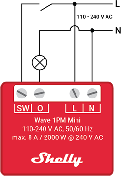
Basic Wiring Diagram
|  |
|  |
|
Legend
| Terminals | Description | Cables | Description |
|---|---|---|---|
| N | Neutral terminal | N | Neutral wire |
| L | Live terminal (110–240 V AC) | L | Live (110–240 V AC) wire |
| SW | Switch/push-button input terminal (controlling O) | — | — |
| I | Load circuit input terminal | S | S button |
| O | Load circuit output terminal | — | — |
About Z-Wave®
Adding the Device to a Z-Wave® Network (Inclusion)
Note! All device outputs (O, O1, O2, etc.) will turn the load on/off briefly (1s on / 1s off) if successfully added/removed.
Note! For Security 2 (S2) inclusion, a PIN code (5 underlined digits) from the Z-Wave® DSK label must be entered.
🔒 IMPORTANT: Never lose the PIN code.
SmartStart Inclusion
- Scan the Z-Wave QR code on the device label using your gateway’s SmartStart feature.
- Connect the device to power.
- Check if the blue LED blinks in Mode 1 (not added).
- Addition starts automatically within seconds.
- Blue LED blinks in Mode 2 during addition.
- Green LED blinks in Mode 1 upon successful addition.
Adding with S Button
- Connect device to power.
- Confirm blue LED blinks in Mode 1.
- Enable add/remove mode on the gateway.
- Press and hold S button until LED turns solid blue.
- Release, then press and hold (>2s) until LED blinks in Mode 3 → release to start Learn mode.
- Blue LED blinks in Mode 2 during inclusion.
- Green LED blinks in Mode 1 if successful.
⚠️ In Setting mode, timeout is 10 seconds before returning to Normal mode.
Adding with Switch/Push-Button
- Connect device to power.
- Confirm blue LED blinks in Mode 1.
- Enable add/remove mode on gateway.
- Toggle the switch/push-button on any SW terminal 3 times within 3 seconds (3 on/off signals).
- Blue LED blinks in Mode 2 during inclusion.
- Green LED blinks in Mode 1 if successful.
Learn mode: State allowing device to receive network info from the gateway.
Removing the Device from a Z-Wave® Network (Exclusion)
Note: Device is removed but custom configurations remain unchanged.
Note! Output toggles briefly (1s on / 1s off) upon successful removal.
Removing with S Button
- Connect device to power.
- Confirm green LED blinks in Mode 1 (added).
- Enable add/remove mode on gateway.
- Press and hold S button until LED turns solid blue.
- Release, then press and hold (>2s) until LED blinks in Mode 3 → release to start Learn mode.
- Blue LED blinks in Mode 2 during removal.
- Blue LED blinks in Mode 1 if successful.
⚠️ Timeout: 10 seconds in Setting mode.
Removing with Switch/Push-Button
- Connect device to power.
- Confirm green LED blinks in Mode 1.
- Enable add/remove mode on gateway.
- Toggle switch/push-button on any SW terminal 3 times within 3 seconds.
- Blue LED blinks in Mode 2 during removal.
- Blue LED blinks in Mode 1 if successful.
Factory Reset
General
After reset, all custom parameters (kWh, associations, routings, etc.) revert to defaults. HOME ID and NODE ID are deleted. Use only when the gateway is missing/inoperable.
With S Button
- Press and hold S button until LED turns solid blue.
- Press S button repeatedly until LED turns solid red.
- Press and hold (>2s) until red LED blinks in Mode 3 → release to start reset.
- During reset: LED turns solid green (~1s), then blue/red blink in Mode 3 (~2s).
- Blue LED blinks in Mode 1 if successful.
With Switch/Push-Button
✅ Only possible within the first minute after power-up.
- Connect device to power.
- Toggle switch/push-button on any SW terminal 5 times within 3 seconds.
- During reset: LED turns solid green (~1s), then blue/red blink in Mode 3 (~2s).
- Blue LED blinks in Mode 1 if successful.
Remotely via Parameter No. 120
Set Parameter 120 to 1 to trigger remote factory reset.
Z-Wave® Security and Device Specific Key (DSK)
The device supports Security 2 (S2) using Strong AES 128 Encryption, making Z-Wave® the most secure IoT platform.
- Authenticated Control
- Out-of-band DSK for inclusion
- Compatible with most implementations
Supports S2 Authenticated, Unauthenticated, and Unsecure inclusion.
🔐 When adding via S2-enabled gateway, the DSK PIN (first 5 digits) is required. Found on the DSK label on the device and inside packaging. Do not remove the label.
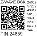
The first five digits are highlighted/underlined. DSK is also represented by a QR code.
Joining node obfuscates its public key (bytes 1–2 set to zero) before RF transmission.
DSK can be used for out-of-band (OOB) authentication via QR scanning.
Z-Wave® Parameters
| Parameter No. | Name | Description | Default | Values |
|---|---|---|---|---|
| 1 | SW (SW1) Switch Type | Defines how SW1 is treated: 0= momentary, 1= toggle (closed=ON), 2= toggle (state change) | 2 | 0, 1, 2 |
| 17 | Restore State After Power Failure | Saves/restores last O (O1) state after outage | 0 | 0=save & restore, 1=do not restore (remains off) |
| 19 | Auto OFF Timer (O1) | Schedule auto-off after ON command. Resets on each ON. | 0 | 0=disabled; 1–32535 = seconds or ms (see Param 25) |
| 20 | Auto ON Timer (O1) | Schedule auto-on after OFF command. Resets on each OFF. | 0 | 0=disabled; 1–32535 = seconds or ms (see Param 25) |
| 23 | O (O1) Contact Type | Relay contact type: 0=NO (normally open), 1=NC (normally closed) | 0 | 0=NO, 1=NC |
| 25 | Timer Unit (O1) | Set timer units: 0=seconds, 1=milliseconds | 0 | 0=sec, 1=ms |
| 36 | Power Report on Change (%) | Minimum % change to report power | 50 | 0=disabled; 1–100% |
| 39 | Min Time Between Reports (O1) | Min interval between power reports | 30 | 0=disabled; 1–120s |
| 91 | Water Alarm Response | Action on water alarm frame | 0 | 0=no action, 1=open relay, 2=close relay |
| 92 | Smoke Alarm Response | Action on smoke alarm frame | 0 | 0=no action, 1=open relay, 2=close relay |
| 93 | CO Alarm Response | Action on CO alarm frame | 0 | 0=no action, 1=open relay, 2=close relay |
| 94 | Heat Alarm Response | Action on heat alarm frame | 0 | 0=no action, 1=open relay, 2=close relay |
| 120 | Factory Reset | Triggers factory reset | 0 | 0=don’t reset, 1=reset |
| 201–203 | Serial Number Parts | Read-only serial number parts | Device-specific | 0x00000000 – 0x7FFFFFFF |
⚠️ Setting Parameter 39 below 30s may cause network congestion.
Z-Wave® Command Classes
- ASSOCIATION_V2 [S0, S2]*
- ASSOCIATION_GRP_INFO_V3 [S0, S2]*
- BASIC_V2 [S0, S2]*
- SWITCH_BINARY_V2 [S0, S2]*
- CONFIGURATION_V4 [S0, S2]*
- DEVICE_RESET_LOCALLY_V1 [S0, S2]*
- FIRMWARE_UPDATE_MD_V5 [S0, S2]*
- INDICATOR_V3 [S0, S2]*
- MANUFACTURER_SPECIFIC_V2 [S0, S2]*
- METER_V6 [S0, S2]*
- MULTI_CHANNEL_ASSOCIATION_V3 [S0, S2]*
- NOTIFICATION_V8 [S0, S2]*
- POWERLEVEL_V1 [S0, S2]*
- SECURITY_V1
- SECURITY_2_V1
- SUPERVISION_V1
- TRANSPORT_SERVICE_V2
- VERSION_V3 [S0, S2]*
- ZWAVEPLUS_INFO_V2
[S2]* = Security S2 Command Class
Z-Wave® Notifications Command Class
Overheat Detected
| Field | Value |
|---|---|
| Notification Type | Heat Alarm |
| Value | 0x04 |
| Event | State |
| Name | Overheat detected |
| Value | 0x02 |
| Version | V2 |
| Device-specific | Yes |
| LED Signalisation | See table |
| Device Reaction | Switch OFF all outputs, send notification |
| Reset Actions | Power cycle, S button press, switch press |
Over-current Detected (O)
| Field | Value |
|---|---|
| Notification Type | Power management |
| Value | 0x08 |
| Event | State |
| Name | Over-current detected |
| Value | 0x06 |
| Version | V3 |
| LED Signalisation | See table |
| Device Reaction | Switch OFF O (O1), send notification |
| Reset Actions | Power cycle, S button press, switch press |
AC Mains Disconnected
| Field | Value |
|---|---|
| Notification Type | Power management |
| Value | 0x08 |
| Event | State |
| Name | AC mains disconnected |
| Value | 0x02 |
| Version | V2 |
| LED Signalisation | See table |
| Device Reaction | Switch OFF all outputs, send notification |
| Reset Actions | Power cycle, S button press, switch press |
Over-voltage Detected
| Field | Value |
|---|---|
| Notification Type | Power management |
| Value | 0x08 |
| Event | State |
| Name | Over-voltage detected |
| Value | 0x07 |
| Version | V3 |
| LED Signalisation | See table |
| Device Reaction | Switch OFF all outputs, send notification |
| Reset Actions | Power cycle, S button press, switch press |
Z-Wave® Associations
Association Group 1 – Lifeline
- Max 9 nodes
- Sends notifications and reports to controlling devices (gateways, remotes)
- Commands:
- INDICATOR_REPORT: LED status
- DEVICE_RESET_LOCALLY_NOTIFICATION: Triggered on request
- SWITCH_BINARY_REPORT: Status change of O (O1)
- NOTIFICATION_REPORT: Overheat, Over-current, Over-voltage, AC mains disconnected
- METER_REPORT: Power consumption (based on Params 36 & 39)
Association Group 2
- Max 9 nodes
- Assigned to SW (SW1) terminal
- Uses BASIC command class
- Triggers: SW (SW1) state change → sends BASIC_SET ON/OFF to associated devices
Association Group 3
- Max 9 nodes
- Assigned to SW (SW1) terminal
- Uses SWITCH_MULTILEVEL command class
- Recommended for push-buttons
- Supports:
- SWITCH_MULTILEVEL_START_LEVEL_CHANGE: Start transition (e.g., dimmer, shutter)
- SWITCH_MULTILEVEL_STOP_LEVEL_CHANGE: Stop ongoing transition
⚠️ Limit to ≤5 devices per group to avoid network delays.
Z-Wave® Important Disclaimer
Z-Wave® wireless communication may not be 100% reliable. Do not rely solely on this device for life-critical or high-value applications. If unrecognized by gateway, manually verify device type and ensure gateway supports Z-Wave Plus™ multi-level devices.
Troubleshooting
For help, visit our support portal: Support
Compatibility
| Gateway | On/Off | SW On/Off | Notes |
|---|---|---|---|
| Home Assistant | ✅ | ✅ | |
| Fibaro HC3 / Z-Wave Engine 3 | ✅ | ✅ | |
| Homey | ✅ | ✅ | |
| Homee Cube Gen 7 | ✅ | ✅ | |
| Homee Cube Gen 5 | ✅ | ⚪ | |
| SmartThings | ✅ | ✅ | With Shelly Wave edge driver |
| Vera Ezlo | ✅ | ✅ | |
| Cozify | ✅ | ✅ |
Legend:
- ✅ Working / Possible
- ⚪ Not Working / Not Possible
- P Partially
- N/T Not Tested
- TBD To Be Done
Function Meaning
| Function | Meaning / Tested |
|---|---|
| On/Off | Responds to app UI On/Off command |
| SW On/Off | Reports On/Off changes via SW input |
| Dimming | Responds to app UI dimming command |
| SW Dimming | Reports dimming state via SW input |
| Watts | Reports watts unsolicited |
| kWh | Reports kWh unsolicited |
| Up/Down | Responds to app UI Up/Down command |
| SW Up/Down | Reports Up/Down changes via SW |
| Slats | Slats respond to app UI command |
| SW Slats | Slats report changes via SW |
| D control | Detached mode: reports scene commands (single/double press, etc.) |
| D Binary | Detached mode: reports binary On/Off via SW |
| Sensor # | Sensor reported in gateway; note type |
Gateway Guides
Useful guides available in the Shelly Knowledge Base
Compliance
- Wave 1PM Mini Multilingual EU Declaration of Conformity (2025-07-22)
- Wave 1PM Mini UK PSTI ACT Statement of Compliance