Shelly Wave Pro 1 – Device Documentation
Note: The product line known as "Shelly Qubino Wave" will now be referred to as "Shelly Wave". This name change will not impact the functionality of any devices. The only modification will be the use of the new name in all future documentation.
Device Identification
- Device: Wave Pro 1
- USA Part number / Ordering Code: QPSW-0A1X16US
- Z-Wave Product type ID:
0x0002 - Z-Wave Product ID:
0x008A - Z-Wave Manufacturer: Shelly Europe Ltd.
- Z-Wave Manufacturer ID:
0x0460
Terminology
- Device: In this document, the term “Device” refers to the Shelly Qubino device that is the subject of this guide.
- Gateway: A Z-Wave® gateway, also referred to as a Z-Wave® controller, Z-Wave® main controller, Z-Wave® primary controller, or Z-Wave® hub, etc., is a device that serves as a central hub for a Z-Wave® smart home network. The term “gateway” is used in this document.
- S button: The Z-Wave® Service button, located on Z-Wave® devices and used for various functions such as adding (inclusion), removing (exclusion), and resetting the device to its factory default settings. The term "S button" is used in this document.
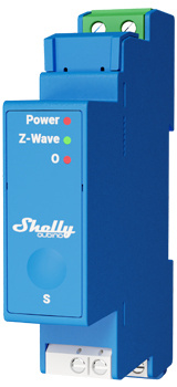
Short Description
The Device is a DIN rail mountable smart switch with potential-free contacts. It controls the on/off function for one electrical device with a load up to 16 A. It is compatible with switches (default) and push-buttons.
Switch Connected to Input Terminal SW (SW1)
If the SW (SW1) is configured as a switch (default), each toggle of the switch will change the output O (O1) state to the opposite state — on, off, on, etc.
- Change switch position once: Change the state of the output O (O1) to the opposite state and send the command to associated devices in groups 2 and 3 (see chapter Z-Wave Association).
Switch-Memory Connected to Input Terminal SW (SW1)
If SW (SW1) is configured as a switch-memory:
- Switching to Close switch-memory contact: Change the state of output O (O1) to On and send command to associated devices in groups 2 and 3.
- Switching to Open switch-memory contact: Change the state of output O (O1) to Off and send command to associated devices in groups 2 and 3.
Push-Button Connected to Input Terminal SW (SW1)
If SW (SW1) is configured as a push-button in the Device settings, each press toggles the output state O (O1):
- Short press: Toggle output state O (O1) and send command to devices in groups 2 and 3.
- Hold: Send command to devices in group 3.
- Release: Send command to devices in group 3.
Switch / Push-Button Connected to Input Terminal SW2
If SW2 is configured as a switch (default), each change in switch status sends an association command to devices in group 4 (on/off) or group 5 (SSLC — root single channel device only), based on the current switch position. (See chapter Z-Wave Association).
Switch-Memory Connected to Input Terminal SW2
If SW2 is configured as a memory switch, any switch state change sends an association command to group 4 (on/off) or group 5 (SSLC — root single-channel devices only), based on the last memorized state during the previous power loss. (See Z-Wave Association chapter).
Push-Button Connected to Input Terminal SW2
- Short press: Toggles between on/off commands, sending a command to devices in group 4 (on/off) or group 5 (SSLC — root single-channel devices only).
- Hold: Sends an association command to initiate level adjustment for devices in group 5 (SSLC — root single-channel devices only).
- Release: Sends an association command to cease level adjustment for devices in group 5 (SSLC — root single-channel devices only).
Switching On/Off Load Connected to O (O1)
The load connected to O (O1) can be switched on/off by:
- Z-Wave command
- Automatic switching via proper settings of Parameters No. 19 and 20
- Pressing the switch/push-button SW (SW1): changes the state of the connected load to the opposite one
Main Applications
- Residential
- MDU (Multi Dwelling Units – apartments, condominiums, hotels, etc.)
- Light commercial (small office buildings, small retail/restaurant/gas station, etc.)
- Government/municipal
- University/college
- Farming
Integrations
Shelly Qubino Wave devices are developed on the world's leading technology for smart homes – Z-Wave.
This means Shelly Qubino Wave works with all certified gateways supporting the Z-Wave communication protocol.
To ensure full functionality, we regularly perform compatibility tests with different Z-Wave gateways.
Simplified Internal Schematics
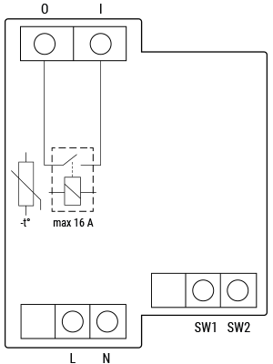
Device Electrical Interfaces
Inputs
- 2 switch/button inputs on screw terminals
- 1 potential-free contact relay input on screw terminal
- 2 power supply inputs on screw terminals: N, L
Outputs
- 1 potential-free contact relay output on screw terminal
Connectivity
Z-Wave – Unsecure, S0 Security, S2 Unauthenticated Security, S2 Authenticated Security
Safety Features
Overheat Protection
- Automatically switches off its own relay
- Sends a Notification Report to the Gateway ("Overheat detected")
- LED reacts as specified (check blinking mode for Overheat detected)
Any of the following actions reset this alarm:
- Power cycle
- Short press on S button
- Press any switch/push-button connected to any SW (SW, SW1, SW2, …) terminal
NOTE: Overheat protection is always active and cannot be disabled.
Additional description under Z-Wave™ Notifications Command Class
Supported Load Types
- Resistive (incandescent bulbs, heating devices)
- Capacitive (capacitor banks, electronic equipment, motor start capacitors)
- Inductive with RC Snubber (LED light drivers, transformers, fans, refrigerators, air-conditioners)
User Interface
S Button and Operating Modes
- Normal mode
- "Setting in progress" mode
- Setting mode (with S button)
- Required to start procedures like inclusion, exclusion, factory reset.
- Limited time operation; automatically returns to Normal mode after completion.
- Entering Setting mode:
- Quickly press and hold the S button until the LED turns solid blue
- An additional quick press changes menu (infinite loop)
- Menu LED status has a 10-second timeout before returning to Normal state
S Button Functions
- Manually add the Device to a Z-Wave network
- Manually remove the Device from a Z-Wave network
- Factory reset the Device
LED Signalisation
Click to see the LED Signalisation
Normal Mode
Removed/Excluded
LED blinks blue in Mode 1 for 10 minutes after every power cycle and after pressing the S button.
Added/Included
LED blinks green in Mode 1 for 10 minutes after every power cycle and after pressing the S button.
Settings in Progress
Factory Reset and Reboot
During reset: LED turns solid green (~1 sec), then blue and red blink rapidly (0.1s on/off) for ~2 sec.Adding / Removing
LED blinks blue in Mode 2.
Firmware Updating OTA
LED blinks blue and red in Mode 2.
Checking Power Supply (230 V AC / 24 V DC)
LED blinks blue and red in Mode 5.
Settings Mode with S Button
Adding / Removing Menu Selected
LED stays solid blue for up to 10 seconds.Adding / Removing Executing
LED blinks blue in Mode 3.
Factory Reset Menu Selected
LED stays solid red for up to 10 seconds.Factory Reset Executing
LED blinks red in Mode 3.
Alarm Mode
- Overheat Detected
LED blinks red in Mode 4: 0.2s On / 0.2s Off × 6 cycles + 2s Off (repeats)
LED Blinking Modes
Click to see the LED blinking modes
| Mode | Blink Pattern |
|---|---|
| Mode 1 | 0.5s On / 2s Off |
| Mode 2 | 0.5s On / 0.5s Off |
| Mode 3 | 0.1s On / 0.1s Off |
| Mode 4 | (1–6 times: 0.2s On / 0.2s Off) + 2s Off |
| Mode 5 | 0.2s On Blue / 0.2s On Red |
Specifications
Error rendering macro 'excerpt-include': User does not have permission to view the page 'DEV:Technical Specifications'.
Basic Wiring Diagram
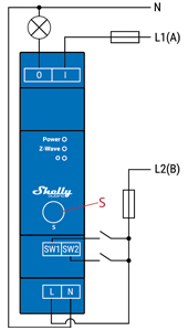
Legend
| Terminals | Description | Wires | Description |
|---|---|---|---|
| N | Neutral terminal | N | Neutral wire |
| L | Live terminal (110–240 V AC) | L1(A) | Load circuit live wire (110–240 V AC) |
| SW | Switch/push-button input terminal (controlling O) | L2(B) | Device power supply live wire (110–240 V AC) |
| SW2 | Switch/push-button input terminal | ||
| I | Load circuit input terminal | ||
| O | Load circuit output terminal |
About Z-Wave®
Adding the Device to a Z-Wave® Network (Inclusion)
Note! All Device outputs (O, O1, O2, etc.) will briefly turn on/off if the Device is successfully added/removed.
Note! For Security 2 (S2) inclusion, a dialog will appear asking for the 5-digit PIN code printed on the Z-Wave® DSK label on the side of the Device and inside the packaging.
IMPORTANT: The PIN must not be lost.
SmartStart Adding (Inclusion)
SmartStart-enabled products can be added by scanning the Z-Wave® QR Code on the Device with a gateway supporting SmartStart.
- Scan the QR code in the gateway app and add the DSK to the provisioning list.
- Connect the Device to power.
- Check if the blue LED is blinking in Mode 1 → indicates not added.
- The Device will auto-add within seconds after power-up.
- Blue LED blinks in Mode 2 during addition.
- Green LED blinks in Mode 1 if successful.
Adding (Inclusion) with the S Button
- Connect the Device to power.
- Confirm blue LED is blinking in Mode 1.
- Enable add/remove mode on the gateway.
- Press and hold S button until LED turns solid blue.
- Release, then press and hold (>2s) until LED blinks in Mode 3 → starts Learn mode.
- Blue LED blinks in Mode 2 during addition.
- Green LED blinks in Mode 1 upon success.
Note: Setting mode has a 10-second timeout before returning to Normal mode.
Adding (Inclusion) with a Switch/Push-Button
- Connect Device to power.
- Confirm blue LED is blinking in Mode 1.
- Enable add/remove mode on the gateway.
- Toggle the switch/push-button on any SW terminal (SW, SW1, SW2) 3 times within 3 seconds → puts Device in Learn mode.
- Blue LED blinks in Mode 2 during addition.
- Green LED blinks in Mode 1 upon success.
Learn mode: State allowing the Device to receive network info from the gateway.
Removing the Device from a Z-Wave® Network (Exclusion)
Note: The Device will be removed from your Z-Wave® network, but custom configurations remain unchanged.
Note: All outputs briefly toggle on/off upon successful removal.
Removing (Exclusion) with the S Button
- Connect Device to power.
- Confirm green LED is blinking in Mode 1 → indicates added.
- Enable add/remove mode on the gateway.
- Press and hold S button until LED turns solid blue.
- Release, then press and hold (>2s) until LED blinks in Mode 3 → starts Learn mode.
- Blue LED blinks in Mode 2 during removal.
- Blue LED blinks in Mode 1 upon success.
Note: Setting mode has a 10-second timeout.
Removing (Exclusion) with a Switch/Push-Button
- Connect Device to power.
- Confirm green LED is blinking in Mode 1.
- Enable add/remove mode on the gateway.
- Toggle the switch/push-button on any SW terminal 3 times within 3 seconds → enters Learn mode.
- Blue LED blinks in Mode 2 during removal.
- Blue LED blinks in Mode 1 upon success.
Factory Reset
General
After factory reset:
- All custom parameters and stored values (kWh, associations, routings, etc.) return to default
- HOME ID and NODE ID are deleted
- Use only when gateway is missing or inoperable
With the S Button
- Press and hold S button until LED turns solid blue.
- Press S button multiple times until LED turns solid red.
- Press and hold (>2s) S button until red LED blinks in Mode 3 → starts reset.
- During reset: LED flashes green (~1s), then blue/red blink in Mode 3 (~2s).
- Blue LED blinks in Mode 1 if successful.
With a Switch/Push-Button
Note: Only possible within the first minute after power-up.
- Connect Device to power.
- Toggle switch/push-button on any SW terminal 5 times within 3 seconds.
- During reset: LED flashes green (~1s), then blue/red blink in Mode 3 (~2s).
- Blue LED blinks in Mode 1 if successful.
Remotely via Parameter (Gateway)
Factory reset can be triggered remotely by setting Parameter No. 120 = 1.
Z-Wave® Security and Device Specific Key (DSK)
The Device supports Security 2 (S2) using Strong AES-128 encryption — making Z-Wave® the most secure IoT platform.
- Authenticated Control
- Out-of-band DSK for inclusion
- Compatible with most implementations
The Device supports:
- S2 Authenticated
- S2 Unauthenticated
- Unsecure inclusion
Note: When adding with S2-enabled gateway, the 5-digit PIN from the DSK label (on device and in packaging) is required. Do not remove the label.
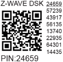
The first five digits are highlighted/underlined. The DSK is also represented as a QR code.
DSK Label and QR Code (Example)
- Joining node obfuscates its public key by setting bytes 1–2 to zero (
0x00) before RF transfer. - DSK may be used for out-of-band (OOB) authentication.
- Gateway can scan QR code to match obfuscated key received via RF.
Z-Wave® Parameters
Parameter No. 1 – SW (SW1) Switch Type
- Value size: 1 Byte
- Default: 2
- Values:
- 0: Momentary switch
- 1: Toggle switch (contact closed = ON)
- 2: Toggle switch (device changes state when switch changes)
Parameter No. 2 – SW2 Switch Type
- Value size: 1 Byte
- Default: 2
- Values:
- 0: Momentary switch (push button)
- 1: Toggle switch (contact closed = ON)
- 2: Toggle switch (device changes state when switch changes)
Parameter No. 17 – Restore State of O (O1) After Power Failure
- Value size: 1 Byte
- Default: 0
- Values:
- 0: Save and restore last state
- 1: Do not save; remains off after power failure
Parameter No. 19 – O (O1) Auto OFF with Timer
- Value size: 2 Bytes
- Default: 0
- Values:
- 0: Auto OFF disabled
- 1–32535: Timer in seconds (or milliseconds — see Param 25)
Timer resets on every ON command (remote or local).
Parameter No. 20 – O (O1) Auto ON with Timer
- Value size: 2 Bytes
- Default: 0
- Values:
- 0: Auto ON disabled
- 1–32535: Timer in seconds (or milliseconds — see Param 25)
Timer resets on every OFF command.
Parameter No. 23 – O (O1) Contact Type – NO/NC
- Value size: 1 Byte
- Default: 0
- Values:
- 0: Normally Open (NO)
- 1: Normally Closed (NC)
| par-NO/NC | Command | Output State |
|---|---|---|
| NO (0) | OFF | OFF (0 V) |
| NO (0) | ON | ON (230 V) |
| NC (1) | OFF | ON (230 V) |
| NC (1) | ON | OFF (0 V) |
Parameter No. 25 – Set Timer Units (s or ms)
- Value size: 1 Byte
- Default: 0
- Values:
- 0: Seconds
- 1: Milliseconds
Parameter No. 91 – Water Alarm
- Value size: 4 Bytes
- Default: 0
- Values:
- 0: No action
- 1: Open relay
- 2: Close relay
Parameter No. 92 – Smoke Alarm
- Value size: 4 Bytes
- Default: 0
- Values:
- 0: No action
- 1: Open relay
- 2: Close relay
Parameter No. 93 – CO Alarm
- Value size: 4 Bytes
- Default: 0
- Values:
- 0: No action
- 1: Open relay
- 2: Close relay
Parameter No. 94 – Heat Alarm
- Value size: 4 Bytes
- Default: 0
- Values:
- 0: No action
- 1: Open relay
- 2: Close relay
Parameter No. 120 – Factory Reset
- Value size: 1 Byte
- Default: 0
- Values:
- 0: Don’t reset
- 1: Perform factory reset
Advanced parameter; may be hidden under "Advanced" tab.
Parameters No. 201–203 – Serial Number Parts
- Read-only, hidden under Advanced tab
- Values:
0x00000000to0x7FFFFFFF
Z-Wave® Command Classes
- ASSOCIATION_V2 [S0, S2]*
- ASSOCIATION_GRP_INFO_V3 [S0, S2]*
- BASIC_V2 [S0, S2]*
- SWITCH_BINARY_V2 [S0, S2]*
- CONFIGURATION_V4 [S0, S2]*
- DEVICE_RESET_LOCALLY_V1 [S0, S2]*
- FIRMWARE_UPDATE_MD_V5 [S0, S2]*
- INDICATOR_V3 [S0, S2]*
- MANUFACTURER_SPECIFIC_V2 [S0, S2]*
- MULTI_CHANNEL_ASSOCIATION_V3 [S0, S2]*
- NOTIFICATION_V8 [S0, S2]*
- POWERLEVEL_V1 [S0, S2]*
- SECURITY_V1
- SECURITY_2_V1
- SUPERVISION_V1
- TRANSPORT_SERVICE_V2
- VERSION_V3 [S0, S2]*
- ZWAVEPLUS_INFO_V2
[S2] = Security S2 Command Class
Z-Wave® Notifications Command Class
Overheat Detected
| Comment | Value |
|---|---|
| Z-Wave Notification Type Name | Heat Alarm |
| Notification Type – Value | 0x04 |
| Notification Event | State |
| Notification Name | Overheat detected |
| Notification Name – Value | 0x02 |
| Notification Version | V2 |
| LED Signalisation | See LED signalisation table |
| Device Reaction | Switch OFF all outputs + send notification |
| Action to Restore | Power cycle, short press S button, press any SW terminal |
Z-Wave® Associations
Associations enable direct device-to-device communication without gateway involvement.
- Max 9 devices per group (fixed)
- Recommended max: 5 per group to avoid delays
- Lifeline Group (Group 1): Reserved for gateway only (1 node allowed)
Association Group 1 – Lifeline Group
- Supports:
INDICATOR_REPORT: LED statusDEVICE_RESET_LOCALLY_NOTIFICATION: triggered on requestSWITCH_BINARY_REPORT: status change of O (O1)NOTIFICATION_REPORT: triggered on Overheat
Association Group 2
- Assigned to SW (SW1)
- Uses Basic command class
- Triggered by SW (SW1)
- Sends
BASIC_SET ON/OFFto associated devices
Association Group 3
- Assigned to SW (SW1)
- Uses Switch Multilevel command class
- Triggered by SW (SW1)
- Recommended for push buttons
- Commands:
SWITCH_MULTILEVEL_START_LEVEL_CHANGESWITCH_MULTILEVEL_STOP_LEVEL_CHANGE
Association Group 4
- Assigned to SW2
- Uses Basic command class
- Sends
BASIC_SET ON/OFFto associated devices
Association Group 5
- Assigned to SW2
- Uses Switch Multilevel command class
- Recommended for push buttons
- Commands:
SWITCH_MULTILEVEL_START_LEVEL_CHANGESWITCH_MULTILEVEL_STOP_LEVEL_CHANGE
Z-Wave® Important Disclaimer
Z-Wave® wireless communication may not be 100% reliable. This Device should not be used in life-critical or high-value scenarios. If the Device is not recognized or behaves incorrectly, manually change the Device type and confirm your gateway supports Z-Wave Plus™ multi-level devices.
Troubleshooting
For help, visit our support portal: Support
Compatibility
| Gateway | On/Off | SW On/Off | Notes |
|---|---|---|---|
| Home Assistant | ✅ | ✅ | |
| Fibaro HC 3 / Z-Wave engine 3 | ✅ | ✅ | |
| Homey | ✅ | ✅ | |
| Homee Cube Gen 7 | ✅ | ✅ | |
| Homee Cube Gen 5 | ✅ | ⚪ | 1* |
| Smart Things | ✅ | ✅ | With Shelly Wave edge driver |
| Jeedom | TBD | TBD | |
| Hubitat | TBD | TBD |
1* Output state changes, but UI fails to reflect updates.
Legend
| Symbol | State |
|---|---|
| ✅ | Working / Possible |
| ⚪ | Not Working / Not Possible |
| P | Partially |
| N/T | Not Tested |
| TBD | To Be Done |
Function Meaning
| Function | Meaning |
|---|---|
| On/Off | Tested if device responds to app UI On/Off command |
| SW On/Off | Tested if device reports On/Off changes via SW input |
| Watts | Tested if Watts are reported unsolicited |
| kWh | Tested if kWh are reported unsolicited |
| Up/Down | Tested if device responds to app UI Up/Down command |
| SW Up/Down | Tested if device reports Up/Down changes via SW input |
| Slats | Tested if slats respond to app UI command |
| SW Slats | Tested if slats report changes via SW |
Gateway Guides
Useful guides available in the Shelly Knowledge Base