Shelly Wave Pro 2 - Device Guide
Note: The product line known as "Shelly Qubino Wave" will now be referred to as "Shelly Wave". This name change will not impact the functionality of any devices. The only modification will be the use of the new name in all future documentation.
Device Identification
- Device: Wave Pro 2
- USA Part number / Ordering Code: QPSW-0A2X16US
- Z-Wave Product Type ID: 0x0002
- Z-Wave Product ID: 0x008C
- Z-Wave Manufacturer: Shelly Europe Ltd.
- Z-Wave Manufacturer ID: 0x0460
Terminology
- Device – In this document, the term “Device” refers to the Shelly Qubino device that is the subject of this guide.
- Gateway – A Z-Wave® gateway (also called a Z-Wave® controller, main controller, primary controller, or hub) acts as a central hub for a Z-Wave® smart home network. The term “gateway” is used throughout this document.
- S button – The Z-Wave® Service button, located on Z-Wave® devices, used for functions such as adding (inclusion), removing (exclusion), and resetting to factory defaults. The term "S button" is used in this document.
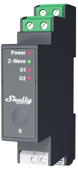
Short Description
The Shelly Wave Pro 2 is a DIN rail-mountable, dual-channel smart switch with potential-free contacts. It controls two independent electrical loads up to 16 A per channel (25 A total). It supports both switches (default) and push-buttons.
Switch Connected to Input Terminal SW (SW1)
If SW (SW1) is configured as a switch (default):
- Single toggle: Changes output O1 state (ON → OFF or vice versa) and sends commands to associated devices in groups 2 and 3 (see Z-Wave Association).
- Double toggle (within 500ms): Interpreted as a double action; sends command to associated dimmers, shutters, etc., in groups 2 and 3.
Switch-Memory Connected to Input Terminal SW (SW1)
If SW (SW1) is configured as a switch-memory:
- Close contact: Output O1 turns ON and sends command to associated devices in groups 2 and 3.
- Open contact: Output O1 turns OFF and sends command to associated devices in groups 2 and 3.
Push-Button Connected to Input Terminal SW (SW1)
If SW (SW1) is configured as a push-button:
- Short press: Toggles output O1 state (ON ↔ OFF) and sends command to associated devices in groups 2 and 3.
- Hold: Sends command to devices in group 3.
- Release: Sends command to devices in group 3.
Switch Connected to Input Terminal SW2
If SW2 is configured as a switch (default):
- Single toggle: Changes output O2 state (ON → OFF or vice versa) and sends command to associated devices in groups 4 and 5.
- Double toggle (within 500ms): Interpreted as a double action; sends command to associated dimmers, shutters, etc., in groups 4 and 5.
Switch-Memory Connected to Input Terminal SW2
If SW2 is configured as a switch-memory:
- Close contact: Output O2 turns ON and sends command to associated devices in groups 4 and 5.
- Open contact: Output O2 turns OFF and sends command to associated devices in groups 4 and 5.
Push-Button Connected to Input Terminal SW2
If SW2 is configured as a push-button:
- Short press: Toggles output O2 state (ON ↔ OFF) and sends command to associated devices in groups 4 and 5.
- Hold: Sends command to devices in group 4.
- Release: Sends command to devices in group 5.
Switching On/Off Load Connected to O (O1)
The load connected to O1 can be controlled via:
- Z-Wave command
- Automatic switching enabled via Parameters No. 19 and 20
- Pressing the switch/push-button SW (SW1): toggles the connected load’s state
Switching On/Off Load Connected to O2
The load connected to O2 can be controlled via:
- Z-Wave command
- Automatic switching enabled via Parameters No. 21 and 22
- Pressing the switch/push-button SW2: toggles the connected load’s state
Main Applications
- Residential
- MDU (Multi Dwelling Units – apartments, condos, hotels, etc.)
- Light commercial (small offices, retail, restaurants, gas stations)
- Government / Municipal
- University / College
- Farming
Integrations
Shelly Wave devices are built on Z-Wave, the world’s leading smart home technology. They work with all certified gateways supporting the Z-Wave protocol.
We regularly test compatibility with various Z-Wave gateways to ensure full functionality.
Simplified Internal Schematics
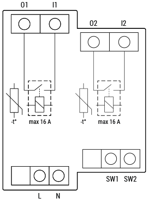
Device Electrical Interfaces
Inputs
- 2 switch/button inputs on screw terminals
- 2 potential-free contact relay inputs on screw terminals
- 2 power supply inputs on screw terminals: N, L
Outputs
- 2 potential-free contact relay outputs on screw terminals
Connectivity
- Z-Wave: Unsecure, S0 Security, S2 Unauthenticated Security, S2 Authenticated Security
Safety Features
Overheat Protection
- Automatically switches off the relay
- Sends Notification Report to the gateway ("Overheat detected")
- LED blinks according to alarm mode (see below)
Reset Conditions: Power cycle, short press on S button, or pressing any switch/push-button on SW (SW1, SW2, etc.)
✅ Note: Overheat protection is always active and cannot be disabled.
🔗 See Notification for Overheat Detected for details.
Supported Load Types
- Resistive (incandescent bulbs, heating devices)
- Capacitive (capacitor banks, electronic equipment, motor start capacitors)
- Inductive with RC Snubber (LED drivers, transformers, fans, refrigerators, air conditioners)
User Interface
S Button and Operating Modes
- Normal Mode
- “Setting in Progress” Mode
- Setting Mode (with S button)
- Required to perform actions like inclusion, exclusion, or factory reset.
- Auto-exits after procedure completion.
- Entering Setting Mode:
- Quickly press and hold the S button until the LED turns solid blue.
- Additional quick press cycles through menus (infinite loop).
- Menu timeout: 10 seconds before returning to Normal mode.
S Button Functions
- Manually add device to Z-Wave network
- Manually remove device from Z-Wave network
- Factory reset device
LED Signalization
| Status | LED Behavior |
|---|---|
| Removed/Excluded | Blinking blue in Mode 1 (10 min after power-up or S button press) |
| Added/Included | Blinking green in Mode 1 (10 min after power-up or S button press) |
| Factory Reset & Reboot | Solid green (~1 sec), then blinking blue/red (0.1s on/off) for ~2 sec |
| Adding/Removing | Blinking blue in Mode 2 |
| OTA Firmware Update | Blinking blue and red in Mode 2 |
| Power Supply Check | Blinking blue and red in Mode 5 |
| Menu Selected (Add/Remove) | Solid blue (max 10 sec) |
| Menu Executing (Add/Remove) | Blinking blue in Mode 3 |
| Menu Selected (Factory Reset) | Solid red (max 10 sec) |
| Menu Executing (Factory Reset) | Blinking red in Mode 3 |
| Overheat Detected | Blinking red in Mode 4: 2× (0.2s ON / 0.2s OFF), 2s OFF, repeating |
📌 See LED Blinking Modes table below for detailed patterns.
LED Blinking Modes
| Mode | Pattern |
|---|---|
| Mode 1 | 0.5s ON / 2s OFF |
| Mode 2 | 0.5s ON / 0.5s OFF |
| Mode 3 | 0.1s ON / 0.1s OFF |
| Mode 4 | (1–6 times) 0.2s ON / 0.2s OFF + 2s OFF |
| Mode 5 | 0.2s ON blue / 0.2s ON red |
Specifications
Error rendering macro 'excerpt-include': User does not have permission to view the page 'DEV:Technical Specifications'.
Basic Wiring Diagram
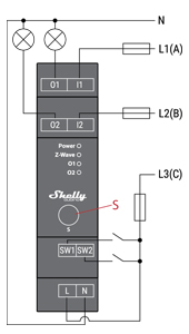
Legend
| Terminal | Description | Wire | Description |
|---|---|---|---|
| N | Neutral terminal | N | Neutral wire |
| L | Live terminal (110–240 V AC) | L1(A) | Load circuit 1 live wire (110–240 V AC) |
| SW | Switch/push-button input terminal (controlling O1) | L2(B) | Load circuit 2 live wire (110–240 V AC) |
| SW2 | Switch/push-button input terminal (controlling O2) | L3(C) | Device power supply live wire (110–240 V AC) |
| I1 | Load circuit input terminal 1 | — | — |
| I2 | Load circuit input terminal 2 | — | — |
| O1 | Load circuit output terminal 1 | — | — |
| O2 | Load circuit output terminal 2 | — | — |
About Z-Wave®
Adding the Device to a Z-Wave® Network (Inclusion)
💡 Note: All outputs (O, O1, O2) will briefly turn ON/OFF (1s each) upon successful addition/removal.
SmartStart Inclusion
- Scan the Z-Wave QR code using your gateway app.
- Add the DSK to the provisioning list.
- Connect the device to power.
- If blue LED blinks in Mode 1 → not added yet.
- The device auto-adds within seconds.
- Blue LED blinks in Mode 2 during inclusion.
- Green LED blinks in Mode 1 if successful.
Adding with S Button
- Connect device to power.
- Confirm blue LED blinks in Mode 1.
- Enable "Add/Remove" mode on gateway.
- Hold S button until LED turns solid blue.
- Release, then hold again (>2s) until LED blinks in Mode 3 → starts Learn mode.
- Blue LED blinks in Mode 2 during inclusion.
- Green LED blinks in Mode 1 if successful.
⏱️ Setting mode timeout: 10 seconds
Adding with Switch/Push-Button
- Connect device to power.
- Confirm blue LED blinks in Mode 1.
- Enable "Add/Remove" mode on gateway.
- Toggle switch/push-button on SW terminal 3 times within 3 seconds → enters Learn mode.
- Blue LED blinks in Mode 2 during inclusion.
- Green LED blinks in Mode 1 if successful.
🔑 Learn mode: State allowing device to receive network info from gateway.
Removing the Device from a Z-Wave® Network (Exclusion)
💡 Note: Custom configurations remain unchanged. Only network membership is removed.
Removing with S Button
- Connect device to power.
- Confirm green LED blinks in Mode 1 → device is added.
- Enable "Add/Remove" mode on gateway.
- Hold S button until LED turns solid blue.
- Release, then hold again (>2s) until LED blinks in Mode 3 → starts Learn mode.
- Blue LED blinks in Mode 2 during removal.
- Blue LED blinks in Mode 1 if successful.
Removing with Switch/Push-Button
- Connect device to power.
- Confirm green LED blinks in Mode 1.
- Enable "Add/Remove" mode on gateway.
- Toggle switch/push-button 3 times within 3 seconds → enters Learn mode.
- Blue LED blinks in Mode 2 during removal.
- Blue LED blinks in Mode 1 if successful.
Factory Reset
General Info
After reset: All custom settings, associations, kWh data, etc., revert to default. HOME ID and NODE ID are deleted. Use only when gateway is unavailable.
With S Button
- Hold S button until LED turns solid blue.
- Press S button repeatedly until LED turns solid red.
- Hold S button (>2s) until red LED blinks in Mode 3 → starts reset.
- During reset: LED turns solid green (~1s), then blue/red blink in Mode 3 (~2s).
- Blue LED blinks in Mode 1 if successful.
With Switch/Push-Button
⚠️ Only possible within first minute after power-up.
- Connect device to power.
- Toggle switch/push-button 5 times within 3 seconds.
- During reset: LED turns solid green (~1s), then blue/red blink in Mode 3 (~2s).
- Blue LED blinks in Mode 1 if successful.
Remotely via Parameter No. 120
Set Parameter 120 = 1 to trigger remote factory reset.
Z-Wave® Security and Device Specific Key (DSK)
The device supports Security 2 (S2) using AES-128 encryption — the most secure IoT platform available.
- Authenticated Control: Out-of-band DSK required for inclusion
- Supports: S2 Authenticated, S2 Unauthenticated, and Unsecure inclusion
🔑 Important: When adding via S2-enabled gateway, you must enter the 5-digit PIN from the DSK label (on device and in packaging). Do not remove the label.
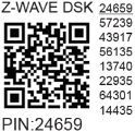
The first five digits are highlighted/underlined. The DSK is also represented via QR code.
For S2 Access Control Class or Authenticated Class, the joining node obfuscates its public key by setting bytes 1–2 to zero before RF transmission.
The gateway can scan the QR code to match the obfuscated public key.
Z-Wave® Parameters
| Parameter | Description | Size | Default | Values & Descriptions |
|---|---|---|---|---|
| 1 – SW (SW1) Switch Type | Defines how SW1 is interpreted | 1 Byte | 2 | 0: momentary switch, 1: toggle (closed=ON), 2: toggle (status change) |
| 2 – SW2 Switch Type | Defines how SW2 is interpreted | 1 Byte | 2 | Same as above |
| 6 – Inputs SW1 & SW2 Swap | Swap operations of SW1/SW2 | 1 Byte | 0 | 0: default (SW1→O1, SW2→O2), 1: swapped (SW1→O2, SW2→O1) |
| 16 – Outputs O1 & O2 Swap | Swap relay outputs | 1 Byte | 0 | 0: default (O1=open, O2=close), 1: reversed |
| 17 – Restore O1 After Power Failure | Save/restore O1 state | 1 Byte | 0 | 0: restore last state, 1: remains OFF |
| 18 – Restore O2 After Power Failure | Save/restore O2 state | 1 Byte | 0 | Same as above |
| 19 – O1 Auto OFF Timer | Auto-turn-off after time | 2 Bytes | 0 | 0: disabled, 1–32535: seconds (or ms if Param 25 = 1) |
| 20 – O1 Auto ON Timer | Auto-turn-on after time | 2 Bytes | 0 | Same as above |
| 21 – O2 Auto OFF Timer | Auto-turn-off after time | 2 Bytes | 0 | Same as above |
| 22 – O2 Auto ON Timer | Auto-turn-on after time | 2 Bytes | 0 | Same as above |
| 23 – O1 Contact Type (NO/NC) | Relay contact type | 1 Byte | 0 | 0: NO, 1: NC |
| 24 – O2 Contact Type (NO/NC) | Relay contact type | 1 Byte | 0 | 0: NO, 1: NC |
| 25 – Timer Units for O1 (s/ms) | Set timer resolution | 1 Byte | 0 | 0: seconds, 1: milliseconds |
| 26 – Timer Units for O2 (s/ms) | Set timer resolution | 1 Byte | 0 | 0: seconds, 1: milliseconds |
| 91 – Water Alarm | Response to water alarm frames | 4 Bytes | 0 | 0: no action, 1: open relay, 2: close relay |
| 92 – Smoke Alarm | Response to smoke alarm frames | 4 Bytes | 0 | Same as above |
| 93 – CO Alarm | Response to CO alarm frames | 4 Bytes | 0 | Same as above |
| 94 – Heat Alarm | Response to heat alarm frames | 4 Bytes | 0 | Same as above |
| 120 – Factory Reset | Trigger factory reset | 1 Byte | 0 | 0: no reset, 1: reset |
| 201–203 – Serial Number Parts | Read-only serial parts | 4 Bytes each | Device-specific | 0x00000000 – 0x7FFFFFFF |
Z-Wave® Command Classes
Core Support
ASSOCIATION_V2[S0, S2]ASSOCIATION_GRP_INFO_V3[S0, S2]BASIC_V2[S0, S2]SWITCH_BINARY_V2[S0, S2]CONFIGURATION_V4[S0, S2]DEVICE_RESET_LOCALLY_V1[S0, S2]FIRMWARE_UPDATE_MD_V5[S0, S2]INDICATOR_V3[S0, S2]MANUFACTURER_SPECIFIC_V2[S0, S2]MULTI_CHANNEL_ASSOCIATION_V3[S0, S2]NOTIFICATION_V8[S0, S2]POWERLEVEL_V1[S0, S2]SECURITY_V1SECURITY_2_V1SUPERVISION_V1TRANSPORT_SERVICE_V2VERSION_V3[S0, S2]ZWAVEPLUS_INFO_V2
Endpoint 1
ASSOCIATION_V2[S0, S2]ASSOCIATION_GRP_INFO_V3[S0, S2]BASIC_V2[S0, S2]MULTI_CHANNEL_V4[S0, S2]NOTIFICATION_V8[S0, S2]SECURITY_V1SECURITY_2_V1SUPERVISION_V1ZWAVEPLUS_INFO_V2
Endpoint 2
ASSOCIATION_V2[S0, S2]ASSOCIATION_GRP_INFO_V3[S0, S2]BASIC_V2[S0, S2]SWITCH_BINARY_V2[S0, S2]MULTI_CHANNEL_V4[S0, S2]NOTIFICATION_V8[S0, S2]SECURITY_V1SECURITY_2_V1SUPERVISION_V1ZWAVEPLUS_INFO_V2
[S2]* = Security 2 Command Class
Z-Wave® Notifications Command Class
Overheat Detected
| Field | Value |
|---|---|
| Notification Type Name | Heat Alarm |
| Notification Type - Value | 0x04 |
| Notification Event | State |
| Notification Name | Overheat Detected |
| Notification Name - Value | 0x02 |
| Version | V2 |
| LED Signalization | Refer to LED table |
| Device Reaction | Switches OFF all outputs + sends notification |
| Restore Action | Power cycle, short S press, or toggle any switch |
Z-Wave® Associations
Associations allow direct communication between devices without gateway involvement.
- Max 9 devices per group (recommended: ≤5)
- Lifeline Group (Group 1): Reserved for gateway only (1 node allowed)
Association Group 1 (Lifeline)
- Endpoint 1 (O1):
SWITCH_BINARY_REPORT,NOTIFICATION_REPORT,INDICATOR_REPORT,DEVICE_RESET_LOCALLY_NOTIFICATION - Endpoint 2 (O2):
SWITCH_BINARY_REPORT
Association Group 2 (Basic Command)
- Assigned to SW1 (SW2 for Endpoint 2)
- Triggers
BASIC_SET ON/OFFbased on switch state
Association Group 3 (Multilevel Command)
- Assigned to SW1 (SW2 for Endpoint 2)
- Recommended for push-buttons
- Triggers:
SWITCH_MULTILEVEL_START_LEVEL_CHANGE,SWITCH_MULTILEVEL_STOP_LEVEL_CHANGE
Association Group 4 (Basic Command)
- Assigned to SW2 (for Endpoint 2)
- Triggers
BASIC_SET ON/OFF
Association Group 5 (Multilevel Command)
- Assigned to SW2 (for Endpoint 2)
- Triggers same multilevel commands as Group 3
Z-Wave® Important Disclaimer
Z-Wave® wireless communication may not be 100% reliable. Do not rely on this device in life-critical situations. If the device is unresponsive or misbehaving, manually set device type and confirm gateway supports Z-Wave Plus™ multi-level devices.
Troubleshooting
For help, visit our support portal: Support
Compatibility Table
| Gateway | On/Off 1 | On/Off 2 | SW On/Off 1 | SW On/Off 2 | Notes |
|---|---|---|---|---|---|
| Home Assistant | ✅ | ✅ | ✅ | ✅ | |
| Fibaro HC3 / Z-Wave engine 3 | ✅ | ✅ | ✅ | ✅ | |
| Homey | ✅ | ✅ | ✅ | ✅ | *H |
| Homee Gen 7 | ✅ | ✅ | ✅ | ✅ | |
| Homee Gen 5 | ❌ P | ❌ P | ⚠️ Blue Star | ⚠️ Blue Star | *1, *2 |
| SmartThings | ✅ | ✅ | ✅ | ✅ | Edge Driver Required |
| Vera Ezlo | ✅ | ✅ | ✅ | ✅ | |
| Cozify | ✅ | ✅ | ✅ | ✅ |
Notes:
*1: Gateway uses standard lifeline; only one control for both outputs in UI.
*2: Output changes, but UI doesn’t reflect update.
H: Fix issues via this solution.
Function Meaning
| Function | Meaning / Tested |
|---|---|
| On/Off | Responds to app UI On/Off command |
| SW On/Off | Reports On/Off changes via SW input |
| Dimming | Responds to app UI dimming command |
| SW Dimming | Reports dimming state changes via SW |
| Watts | Reports watts unsolicited |
| kWh | Reports kWh unsolicited |
| Up/Down | Responds to app UI Up/Down command |
| SW Up/Down | Reports Up/Down changes via SW |
| Slats | Slats respond to app UI command |
| SW Slats | Slats report changes via SW |
| D control | Reports scene commands (single/double press, etc.) |
| D Binary | Reports binary On/Off via SW |
| Sensor # | Sensor visualized in gateway; note type |
Legend
| Symbol | State |
|---|---|
| ✅ | Working / Possible |
| ⚠️ | Not Working / Not Possible |
| P | Partially |
| N/T | Not Tested |
| TBD | To Be Done |
Gateway Guides
Useful guides available in the Shelly Knowledge Base