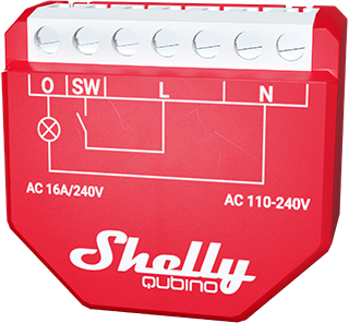
Shelly Wave 1PM – Device Documentation
Note: The product line known as "Shelly Qubino Wave" will now be referred to as "Shelly Wave". This name change will not impact the functionality of any devices. The only modification will be the use of the new name in all future documentation.
Device Identification
- Device: Wave 1PM
- AU Part number / Ordering Code: QNSW-001P16AU
- Z-Wave Product type ID:
0x0002 - Z-Wave Product ID:
0x0084 - Z-Wave Manufacturer: Shelly Europe Ltd.
- Z-Wave Manufacturer ID:
0x0460
Terminology
- Device: In this document, the term “Device” refers to the Shelly Qubino device covered by this guide.
- Gateway: A Z-Wave® gateway (also called a Z-Wave® controller, hub, or primary controller) that acts as the central hub for a Z-Wave® smart home network. The term “gateway” is used throughout this document.
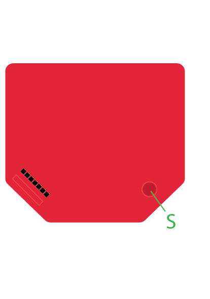
- S button: The Z-Wave® Service button located on Z-Wave® devices. Used for functions like inclusion/exclusion and factory reset. The term "S button" is used here.
Short Description
The Shelly Wave 1PM is a single-channel device that enables control of on/off states for one electrical load (e.g., light bulb, ceiling fan, IR heater). It also measures power consumption of the connected device. Compatible with both switches (default) and push-buttons.
Switch Connected to Input Terminal SW (SW1)
If SW (SW1) is configured as a switch (default), each toggle changes the output state O (O1) to the opposite state — ON → OFF → ON → etc.
- Change switch position once:
- Toggle the output state O (O1) to the opposite state.
- Send a command to associated devices in groups 2 and 3 (see Z-Wave Associations).
Main Applications
- Residential
- MDU (Multi Dwelling Units – apartments, condos, hotels, etc.)
- Light Commercial (small offices, retail stores, restaurants, gas stations, etc.)
- Government/Municipal
- University/College
Integrations
Shelly Wave devices are built on Z-Wave, the world’s leading smart home technology.
This means they work with all certified gateways supporting the Z-Wave protocol.
We regularly test compatibility across various Z-Wave gateways to ensure full functionality.
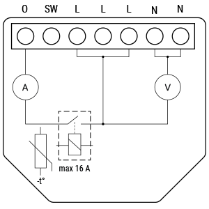
Simplified Internal Schematics
Device Electrical Interfaces
Inputs
- 1 switch/button input on screw terminal
- 5 power supply inputs on screw terminals: 2 × N, 3 × L
Outputs
- 1 relay output with power measurement on screw terminal
Connectivity
Z-Wave: Unsecure, S0 Security, S2 Unauthenticated Security, S2 Authenticated Security
Safety Features
Overheat Protection
- Automatically switches off the relay
- Sends Notification Report to the gateway ("Overheat detected")
- LED blinks according to alarm mode (see LED signalization table)
Reset triggers: Power cycle, short press on S button, or pressing any switch/push-button connected to SW (SW1, SW2, etc.)
✅ Note: Overheat protection is always active and cannot be disabled.
See Z-Wave Notifications Command Class for details.
Over-current Protection
If current exceeds 16A + 10% (max switching current +10%) for more than 5 seconds, the device:
- Switches off the relay
- Sends Notification Report ("Over-current detected")
- LED blinks accordingly
Reset triggers: Same as above — power cycle, S button press, or switch input.
✅ Note: Over-current protection is always active and cannot be disabled.
See Z-Wave Notifications Command Class for details.
Supported Load Types
- Resistive (incandescent bulbs, heating devices)
- Capacitive (capacitor banks, electronic equipment, motor start capacitors)
- Inductive with RC Snubber (LED drivers, transformers, fans, refrigerators, air conditioners)
User Interface
S Button and Operating Modes
- Normal Mode
- Setting in Progress Mode
- Setting Mode (with S button)
- Required to perform actions like inclusion, exclusion, or factory reset.
- Has a limited time window; after completion, returns automatically to Normal Mode.
Entering Setting Mode:
- Quickly press and hold the S button until the LED turns solid blue.
- An additional quick press cycles through menu options (infinite loop).
- Menu LED status times out after 10 seconds → reverts to Normal Mode.
S Button Functions
- Manually add the device to a Z-Wave network (inclusion)
- Manually remove the device from a Z-Wave network (exclusion)
- Perform factory reset
LED Signalisation
Click to expand:
Click to see LED signalisation
Normal Mode
Removed/Excluded:
- Blinking blue in Mode 1 for 10 minutes after power cycle or S button press

- Blinking blue in Mode 1 for 10 minutes after power cycle or S button press
Added/Included:
- Blinking green in Mode 1 for 10 minutes after power cycle or S button press

- Blinking green in Mode 1 for 10 minutes after power cycle or S button press
Settings in Progress
- Factory Reset & Reboot:
- Solid green (~1 sec), then blinking blue/red (0.1s on/off) for ~2 sec
- Adding/Removing:
- Blinking blue in Mode 2

- Blinking blue in Mode 2
- Firmware OTA Update:
- Blinking blue & red in Mode 2

- Blinking blue & red in Mode 2
- Power Supply Check (230V AC / 24V DC):
- Blinking blue & red in Mode 5

- Blinking blue & red in Mode 5
Settings Mode (with S Button)
- Menu Selected (Add/Remove): Solid blue for up to 10 seconds
- During Add/Remove Process: Blinking blue in Mode 3

- Menu Selected (Factory Reset): Solid red for up to 10 seconds
- During Factory Reset: Blinking red in Mode 3

Alarm Mode
- Over-current Detected:
- Blinking red in Mode 4: 1× (0.2s On/Off), 2s Off → repeat

- Blinking red in Mode 4: 1× (0.2s On/Off), 2s Off → repeat
- Overheat Detected:
- Blinking red in Mode 4: 2× (0.2s On/Off), 2s Off → repeat

- Blinking red in Mode 4: 2× (0.2s On/Off), 2s Off → repeat
- Power Supply Fault:
- Blinking red in Mode 4: 3× (0.2s On/Off), 2s Off → repeat

- Blinking red in Mode 4: 3× (0.2s On/Off), 2s Off → repeat
LED Blinking Modes
| Mode | Description |
|---|---|
| Mode 1 | 0.5s On / 2s Off |
| Mode 2 | 0.5s On / 0.5s Off |
| Mode 3 | 0.1s On / 0.1s Off |
| Mode 4 | (1–6×) 0.2s On/Off + 2s Off |
| Mode 5 | 0.2s On blue / 0.2s On red |
Specifications
| Parameter | Value |
|---|---|
| Power Supply | 110–240 V AC, 50/60 Hz |
| Power Consumption | < 0.3 W |
| Power Measurement (W) | Yes |
| Max Switching Voltage AC | 240 V |
| Max Switching Current AC | 16 A |
| Overheating Protection | Yes |
| Overload Protection | Yes |
| Communication Range | Up to 40 m indoors (131 ft.), depends on environment |
| Z-Wave® Repeater | Yes |
| CPU | Z-Wave® S800 |
| Z-Wave® Frequency Bands | 919.8 MHz |
| Max Radio Power | < 25 mW |
| Dimensions (H × W × D) | 37 × 42 × 16 ±0.5 mm (1.46 × 1.65 × 0.63 ±0.02 in) |
| Weight | 27 g / 0.95 oz |
| Mounting | Wall console |
| Screw Terminal Torque | 0.4 Nm / 3.5 lbin |
| Conductor Cross Section | 0.5 – 1.5 mm² / 20 – 16 AWG |
| Stripped Length | 5 – 6 mm / 0.20 – 0.24 in |
| Shell Material | Plastic |
| Color | Red |
| Ambient Temperature | -20°C to 40°C (-5°F to 105°F) |
| Humidity | 30% to 70% RH |
| Max Altitude | 2000 m / 6562 ft |
Basic Wiring Diagram
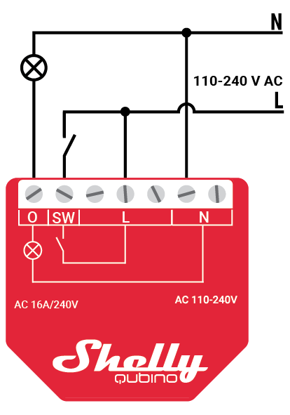
Legend
| Terminal | Function | Wire | Function |
|---|---|---|---|
| N | Neutral terminal | N | Neutral wire |
| L | Live terminal (110–240 V AC) | L | Live (110–240 VAC) wire |
| SW | Switch/Push-button input terminal (controls O) | — | — |
| O | Load circuit output terminal | — | — |
About Z-Wave®
Adding the Device to a Z-Wave® Network (Inclusion)
Note! All outputs (O, O1, etc.) will briefly turn ON/OFF (1s on, 1s off) if the device is successfully added/removed.
Important: For Security 2 (S2) inclusion, enter the PIN code (5 underlined digits) found on the Z-Wave® DSK label (on device and in packaging). Do not lose this label.
SmartStart Inclusion
- Scan the QR code on the device using a SmartStart-compatible gateway.
- Connect the device to power.
- Confirm blue LED is blinking in Mode 1 → indicates not yet added.
- The device auto-adds within seconds.
- Blue LED blinks in Mode 2 during inclusion.
- Green LED blinks in Mode 1 if successful.
Adding with S Button
- Connect to power.
- Confirm blue LED blinking in Mode 1.
- Enable "add/remove" mode on gateway.
- Press and hold S button until LED turns solid blue.
- Release, then press and hold (>2s) until LED blinks in Mode 3 → starts Learn mode.
- Blue LED blinks in Mode 2 during inclusion.
- Green LED blinks in Mode 1 if successful.
⚠️ Timeout: Setting mode exits after 10 seconds if no action taken.
Adding with Switch/Push-Button
- Connect to power.
- Confirm blue LED blinking in Mode 1.
- Enable "add/remove" mode on gateway.
- Toggle switch/push-button on any SW terminal 3 times within 3 seconds → puts device in Learn mode.
- Blue LED blinks in Mode 2 during inclusion.
- Green LED blinks in Mode 1 if successful.
Learn Mode: State allowing device to receive network info from gateway.
Removing the Device from a Z-Wave® Network (Exclusion)
Note: Custom configurations remain intact; only network membership is removed.
Removing with S Button
- Connect to power.
- Confirm green LED blinking in Mode 1 → device is added.
- Enable "add/remove" mode on gateway.
- Press and hold S button until LED turns solid blue.
- Release, then press and hold (>2s) until LED blinks in Mode 3 → starts Learn mode.
- Blue LED blinks in Mode 2 during removal.
- Blue LED blinks in Mode 1 if successful.
Removing with Switch/Push-Button
- Connect to power.
- Confirm green LED blinking in Mode 1.
- Enable "add/remove" mode on gateway.
- Toggle switch/push-button on any SW terminal 3 times within 3 seconds.
- Blue LED blinks in Mode 2 during removal.
- Blue LED blinks in Mode 1 if successful.
Factory Reset
Note: After reset, all custom settings (kWh, associations, routing, etc.) revert to default. HOME ID and NODE ID are deleted. Use only when gateway is unavailable.
With S Button
- Press and hold S button until LED turns solid blue.
- Press S button repeatedly until LED turns solid red.
- Hold S button (>2s) until red LED blinks in Mode 3 → starts reset.
- During reset: solid green (~1s), then blue/red blink in Mode 3 (~2s).
- Blue LED blinking in Mode 1 → success.
With Switch/Push-Button
✅ Only possible within first minute after power-up.
- Connect to power.
- Toggle switch/push-button on any SW terminal 5 times within 3 seconds.
- During reset: solid green (~1s), then blue/red blink in Mode 3 (~2s).
- Blue LED blinking in Mode 1 → success.
Remotely via Gateway Parameter
Set Parameter No. 120 = 1431655765 (hex: 0x55555555) to trigger remote factory reset.
Z-Wave® Security and Device Specific Key (DSK)
The device supports Security 2 (S2) using AES-128 encryption, making it one of the most secure IoT platforms.
S2 Features:
- Out-of-band DSK authentication
- Supports S2 Authenticated, Unauthenticated, and Unsecure inclusion
🔑 DSK PIN Required for S2 inclusion. Found on:
- Side label of device
- Label inside packaging
⚠️ Never remove or lose the DSK label.
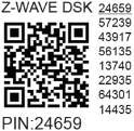
- First five digits are highlighted/underlined → PIN code
- Full DSK also represented via QR code
Obfuscation: Joining node sets bytes 1–2 to zero before sending public key via RF.
Z-Wave® Parameters
| Parameter | Description | Size | Default | Values & Notes |
|---|---|---|---|---|
| No. 1 – SW (SW1) Switch Type | Defines how SW input is interpreted | 1 Byte | 2 | 0 = momentary 1 = toggle (closed=ON) 2 = toggle (state change) |
| No. 17 – Restore State After Power Failure | Whether to restore last state | 1 Byte | 0 | 0 = restore 1 = remain OFF |
| No. 19 – Auto OFF Timer (O1) | Schedule automatic OFF | 2 Bytes | 0 | 0 = Disabled 1–32535 = seconds (or ms if Param 25 set) |
| No. 20 – Auto ON Timer (O1) | Schedule automatic ON | 2 Bytes | 0 | 0 = Disabled 1–32535 = seconds (or ms) |
| No. 23 – O (O1) Contact Type (NO/NC) | Relay contact type | 1 Byte | 0 | 0 = NO 1 = NC |
| No. 25 – Timer Unit (s/ms) | Set timer resolution | 1 Byte | 0 | 0 = seconds 1 = milliseconds |
| No. 36 – Power Report Change (%) | Min % change to report | 1 Byte | 50 | 0 = disabled 1–100 = % threshold |
| No. 39 – Min Time Between Reports (O1) | Minimum interval between reports | 1 Byte | 30 | 0 = disabled 1–120 = seconds |
| No. 91 – Water Alarm Response | Action on water alarm frame | 4 Bytes | 0 | 0 = no action 1 = open relay 2 = close relay |
| No. 92 – Smoke Alarm Response | Action on smoke alarm | 4 Bytes | 0 | Same as above |
| No. 93 – CO Alarm Response | Action on CO alarm | 4 Bytes | 0 | Same as above |
| No. 94 – Heat Alarm Response | Action on heat alarm | 4 Bytes | 0 | Same as above |
| No. 120 – Factory Reset (Remote) | Trigger factory reset | 4 Bytes | 0 | 0 = no reset 1431655765 = reset (0x55555555) |
| No. 201–203 – Serial Number Parts | Read-only device serial parts | 4 Bytes each | Device-specific | Hidden under Advanced tag |
📌 Note: Power reports are limited by both % change (Param 36) and minimum interval (Param 39).
Z-Wave® Command Classes
| Command Class | Security Support |
|---|---|
| ASSOCIATION_V2 | S0, S2 |
| ASSOCIATION_GRP_INFO_V3 | S0, S2 |
| BASIC_V2 | S0, S2 |
| SWITCH_BINARY_V2 | S0, S2 |
| CONFIGURATION_V4 | S0, S2 |
| DEVICE_RESET_LOCALLY_V1 | S0, S2 |
| FIRMWARE_UPDATE_MD_V5 | S0, S2 |
| INDICATOR_V3 | S0, S2 |
| MANUFACTURER_SPECIFIC_V2 | S0, S2 |
| METER_V6 | S0, S2 |
| MULTI_CHANNEL_ASSOCIATION_V3 | S0, S2 |
| NOTIFICATION_V8 | S0, S2 |
| POWERLEVEL_V1 | S0, S2 |
| SECURITY_V1 | — |
| SECURITY_2_V1 | — |
| SUPERVISION_V1 | — |
| TRANSPORT_SERVICE_V2 | — |
| VERSION_V3 | S0, S2 |
| ZWAVEPLUS_INFO_V2 | — |
[S2]*= Security S2 supported
Z-Wave® Notifications Command Class
Overheat Detected
| Field | Value |
|---|---|
| Notification Type Name | Heat Alarm |
| Type Value | 0x04 |
| Event | State |
| Notification Name | Overheat detected |
| Name Value | 0x02 |
| Version | V2 |
| Device Specific | Yes |
| LED Signalisation | See table above |
| Device Reaction | Switch OFF output, send notification |
| Restore Actions | Power cycle, S button press, switch press |
Over-current Detected O (O1)
| Field | Value |
|---|---|
| Notification Type Name | Power management |
| Type Value | 0x08 |
| Event | State |
| Notification Name | Over-current detected |
| Name Value | 0x06 |
| Version | V3 |
| Device Specific | Yes |
| LED Signalisation | See table above |
| Device Reaction | Switch OFF O1, send notification |
| Restore Actions | Power cycle, S button press, switch press |
AC Mains Disconnected
| Field | Value |
|---|---|
| Notification Type Name | Power management |
| Type Value | 0x08 |
| Event | State |
| Notification Name | AC mains disconnected |
| Name Value | 0x02 |
| Version | V2 |
| Device Specific | Yes |
| LED Signalisation | See table above |
| Device Reaction | Switch OFF all outputs, send notification |
| Restore Actions | Power cycle, S button press, switch press |
Z-Wave® Associations
Association Group 1 – Lifeline
- Purpose: Reports device status and health
- Allowed Nodes: 1 (default: Gateway)
- Supported Command Classes:
INDICATOR_REPORT: LED statusDEVICE_RESET_LOCALLY_NOTIFICATION: Triggered upon requestSWITCH_BINARY_REPORT: Output state changesNOTIFICATION_REPORT: Overheat alertsMETER_REPORT: Power usage (based on Params 36–43)
Association Group 2
- Allowed Nodes: 9
- Trigger: SW (SW1) terminal
- Function: Sends
BASIC_SET ON/OFFto associated device - Command Class:
BASIC_SET
Association Group 3
- Allowed Nodes: 9
- Trigger: SW (SW1) terminal
- Function: Sends
SWITCH_MULTILEVEL_START_LEVEL_CHANGEorSTOP - Command Classes:
SWITCH_MULTILEVEL_START_LEVEL_CHANGESWITCH_MULTILEVEL_STOP_LEVEL_CHANGE
Z-Wave® Important Disclaimer
Z-Wave® communication may not be 100% reliable. Do not rely solely on this device for life-critical applications. If unrecognized or misbehaving, manually verify device type and ensure gateway supports Z-Wave Plus™ multi-level devices.
Troubleshooting
For help, visit: Support Portal
Compatibility with Gateways
| Gateway | On/Off | SW On/Off | Watts | kWh | Notes |
|---|---|---|---|---|---|
| Home Assistant | ✅ | ✅ | ✅ | ✅ | |
| Fibaro HC3 / Z-Wave Engine 3 | ✅ | ✅ | ✅ | ✅ | |
| Homey | ✅ | ✅ | ✅ | ✅ | |
| Homee Cube Gen 7 | ✅ | ✅ | ✅ | ✅ | |
| Homee Cube Gen 5 | ✅ | ✅ | ✅ | ✅ | |
| SmartThings | ✅ | ✅ | ✅ | ✅ | With Shelly Wave edge driver |
| Vera Ezlo | ✅ | ✅ | ✅ | ✅ | |
| Cozify | ✅ | ✅ | ✅ | ✅ | |
| Hubitat | ✅ | ✅ | ✅ | ❌ N/T |
🔎 Legend:
- ✅ Working / Possible
- ⚪ Not Working / Not Possible
- P Partially
- N/T Not Tested
- TBD To Be Done
Gateway Guides
Find useful guides at: Shelly Knowledge Base – Z-Wave
Printed User Guide
Download PDF: Wave_1PM_ANZ_user_guide_print_V2.pdf
✅ Document updated: Shelly Wave 1PM AU