Shelly Wave 2PM (AU) - User Guide
Note: The product line known as "Shelly Qubino Wave" will now be referred to as "Shelly Wave". This name change will not impact the functionality of any devices. The only modification will be the use of the new name in all future documentation.
Device Identification
- Device name:
Wave 2PM - AUS Part number / Ordering Code:
QNSW-002P16AU - Z-Wave Product type ID:
0x0002 - Z-Wave Product ID:
0x0081 - Z-Wave Manufacturer: Shelly Europe Ltd.
- Z-Wave Manufacturer ID:
0x0460
Terminology
- Device: In this document, the term “Device” refers to the Wave 2PM device.
- Gateway: A Z-Wave® gateway, also called a Z-Wave® controller, main controller, primary controller, or hub. The term “gateway” is used here.
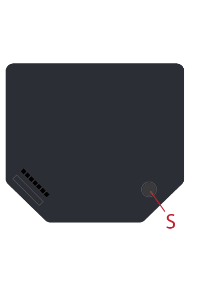
- S button: The Z-Wave® Service button located on Z-Wave® devices. Used for inclusion, exclusion, and factory reset. Referred to as "S button".
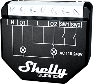
Short Description
The Wave 2PM is a single device that enables remote control of two electrical loads such as bulbs, ceiling fans, and IR heaters. It switches (on/off) two independent loads and measures their power consumption separately and in total. Compatible with switches (default) and push-buttons.
Switch Connected to Input Terminal SW (SW1)
If configured as a switch (default), each toggle changes the output state O (O1) to the opposite state — ON, OFF, ON, etc.
- Change switch position once:
Toggle the switch → Change output state O1 → Send command to associated devices in groups 2 and 3
(See: Z-Wave Associations)
Switch Connected to Input Terminal SW2
Same behavior as above, but controls output O2.
- Change switch position once:
Toggle the switch → Change output state O2 → Send command to associated devices in groups 2 and 3
(See: Z-Wave Associations)
Main Applications
- Residential
- MDU (Multi Dwelling Units – apartments, condos, hotels, etc.)
- Light commercial (small offices, retail, restaurants, gas stations)
- Government / Municipal
- University / College
Integrations
Shelly Qubino Wave devices are built on Z-Wave, the world’s leading smart home technology.
- Works with all certified gateways supporting Z-Wave communication.
- Regular compatibility testing ensures full function support across gateways.
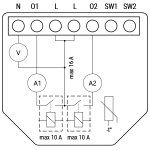
Simplified Internal Schematics
Device Electrical Interfaces
Inputs
- 2 switch/button inputs on screw terminals
- 3 power supply inputs on screw terminals: N and L
Outputs
- 2 relay outputs with power measurement on screw terminals
Connectivity
- Z-Wave: Unsecure, S0 Security, S2 Unauthenticated Security, S2 Authenticated Security
Safety Features
Overheat Protection
- Automatically switches off the relay
- Sends Notification Report to gateway: Overheat detected
- LED reacts accordingly (check blinking mode)
Reset triggers: Power cycle, Remote reboot (via Parameter 117), short press on S button, or pressing any connected switch/button.
⚠️ Note: Overheat protection is always active and cannot be disabled.
See: Z-Wave Notifications Command Class
Over-current Protection
- If current exceeds 16A + 10% for more than 5 seconds:
- Switches off the relay
- Sends Notification Report: Over-current detected
- LED blinks accordingly
Reset triggers: Same as overheat protection.
⚠️ Note: Over-current protection is always active and cannot be disabled.
See: Z-Wave Notifications Command Class
Supported Load Types
- Resistive (incandescent bulbs, heating devices)
- Capacitive (capacitor banks, electronic equipment, motor start capacitors)
- Inductive with RC Snubber (LED drivers, transformers, fans, refrigerators, air conditioners)
User Interface
S Button and Operating Modes
- Normal mode
- Setting in progress mode
- Setting mode (with S button)
- Required for procedures like inclusion, exclusion, factory reset.
- Limited operation time; auto-exits to Normal mode after completion.
Entering Setting Mode:
- Quickly press and hold the S button until the LED turns solid blue.
- An additional quick press cycles through menu options.
- Menu timeout: 10 seconds before returning to Normal mode.
S Button Functions
- Manually add device to Z-Wave network
- Manually remove device from Z-Wave network
- Factory reset device
LED Signalisation
| Mode | Blinking Pattern | Meaning |
|---|---|---|
| Mode 1 | 0.5s On / 2s Off | Normal mode |
| Mode 2 | 0.5s On / 0.5s Off | Adding/Removing, OTA update, power check |
| Mode 3 | 0.1s On / 0.1s Off | Active menu selection |
| Mode 4 | 1–6x: 0.2s On / 0.2s Off + 2s Off | Alarm states (Overcurrent, Overheat, Power fault) |
| Mode 5 | 0.2s On (blue) / 0.2s On (red) | Power supply check |
Detailed LED States:
Normal Mode
- Removed/Excluded: Blue blink (Mode 1) for 10 min after power-up or S button press

- Added/Included: Green blink (Mode 1) for 10 min after power-up or S button press

Settings in Progress
- Factory Reset & Reboot: Solid green (~1s), then blue+red blink rapidly (~2s)
- Adding/Removing: Blue blink (Mode 2)

- OTA Update: Blue+Red blink (Mode 2)

- Power Supply Check: Blue+Red blink (Mode 5)

Settings Mode (S Button Selected)
- Add/Remove Menu Selected: Solid blue (max 10 sec)
- Add/Remove Executing: Blue blink (Mode 3)

- Factory Reset Menu Selected: Solid red (max 10 sec)
- Factory Reset Executing: Red blink (Mode 3)

Alarm Mode
- Over-current Detected: 1x (0.2s On / 0.2s Off) + 2s Off repeated

- Overheat Detected: 2x (0.2s On / 0.2s Off) + 2s Off repeated

- Power Supply Fault: 3x (0.2s On / 0.2s Off) + 2s Off repeated

Specifications
| Feature | Value |
|---|---|
| Power Supply | 110–240 V AC, 50/60 Hz |
| Power Consumption | < 0.3 W |
| Power Measurement | Yes |
| Max Switching Voltage (AC) | 240 V |
| Max Switching Current (AC) | 10 A per channel, 16 A total, 18 A peak |
| Overheating Protection | Yes |
| Over-current Protection | Yes |
| Over-voltage Protection | Yes |
| Range (Indoor) | Up to 40 m (131 ft.) – depends on environment |
| Z-Wave Repeater | Yes |
| CPU | Z-Wave® S800 |
| Z-Wave Frequency Band | 919.8 MHz |
| Max Radio Power | < 25 mW |
| Dimensions (H x W x D) | 37 × 42 × 16 ± 0.5 mm / 1.46 × 1.65 × 0.63 ± 0.02 in |
| Weight | 29 g |
| Mounting | Wall console |
| Screw Terminal Torque | 0.4 Nm / 3.5 lbin |
| Conductor Cross Section | 0.5 – 1.5 mm² / 20 – 16 AWG |
| Stripped Length | 5 – 6 mm / 0.20 – 0.24 in |
| Shell Material | Plastic |
| Color | Black |
| Ambient Temperature | -20°C to 40°C / -5°F to 105°F |
| Humidity | 30% to 70% RH |
| Max Altitude | 2000 m / 6562 ft. |
Basic Wiring Diagram
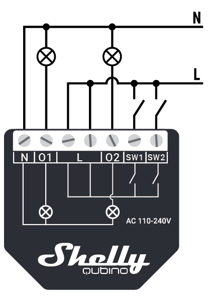
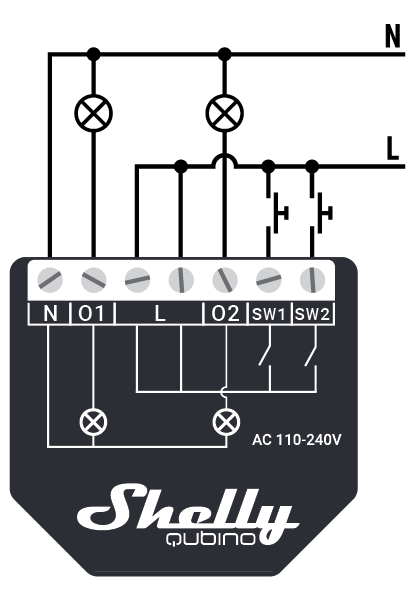
Legend
| Terminal | Function | Wire | Function |
|---|---|---|---|
| N | Neutral terminal | N | Neutral wire |
| L | Live terminal (110–240 V AC) | L | Live wire |
| SW1 | Switch/push-button input (controls O1) | — | — |
| SW2 | Switch/push-button input (controls O2) | — | — |
| O1 | Load circuit 1 output terminal | — | — |
| O2 | Load circuit 2 output terminal | — | — |
About Z-Wave®
Adding the Device to a Z-Wave Network (Inclusion)
Note: All outputs (O, O1, O2) will briefly turn on/off during successful addition/removal.
SmartStart Inclusion
- Scan QR code on device label using gateway app.
- Add Security 2 (S2) Device Specific Key (DSK) to provisioning list.
- Connect device to power.
- Confirm slow blue LED blink → indicates not yet added.
- Automatic inclusion within seconds after power-on.
- Fast blue blink during adding process.
- Slow green blink if successfully added.
Adding with S Button
- Connect device to power.
- Confirm slow blue LED blink.
- Enable add/remove mode on gateway.
- Press and hold S button until LED turns solid blue.
- Release, then press and hold (>2s) until LED blinks slowly → releases to learn mode.
- Fast blue blink during adding.
- Slow green blink if success.
⚠️ Setting mode has a 10-second timeout.
Adding with Switch/Push-Button
- Connect device to power.
- Confirm slow blue LED blink.
- Enable add/remove mode on gateway.
- Toggle switch/push-button on SW terminal 3 times within 3 seconds.
- Fast blue blink during adding.
- Slow green blink if success.
Learn Mode: State allowing device to receive network info from gateway.
Removing the Device from Z-Wave Network (Exclusion)
Note: Custom settings preserved; only network association removed.
Removing with S Button
- Connect device to power.
- Confirm slow green LED blink → device is added.
- Enable add/remove mode on gateway.
- Press and hold S button until LED turns solid blue.
- Release, then press and hold (>2s) until LED blinks slowly → starts learn mode.
- Fast blue blink during removal.
- Slow blue blink if successful.
Removing with Switch/Push-Button
- Connect device to power.
- Confirm slow green LED blink.
- Enable add/remove mode on gateway.
- Toggle switch/push-button 3 times within 3 seconds.
- Fast blue blink during removal.
- Slow blue blink if successful.
Factory Reset
Note: Resets all custom parameters, associations, routing, kWh data, HOME ID, NODE ID.
With S Button
- Press and hold S button until LED turns solid blue.
- Press S button repeatedly until LED turns solid red.
- Hold S button (>2s) until LED blinks fast → starts reset.
- LED flashes green → blue/red rapid blink (~2s).
- Slow blue blink if successful.
With Switch/Push-Button
Only possible within first minute after power-up.
- Connect device to power.
- Toggle switch/push-button 5 times within 3 seconds.
- LED flashes green → blue/red rapid blink (~2s).
- Slow blue blink if successful.
Remotely via Parameter No. 120
Set Parameter 120 = 1 → triggers factory reset.
Z-Wave® Security and Device Specific Key (DSK)
- Supports Security 2 (S2) using AES-128 encryption.
- Requires S2-enabled gateway.
- Authentication types supported: Out-of-band DSK, S2 Authenticated, S2 Unauthenticated, Unsecure.
🔐 PIN Code required for S2 inclusion (first 5 digits of DSK). Found on side label and packaging.
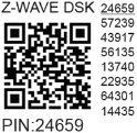
⚠️ Never remove DSK label. Keep backup in packaging.
Z-Wave® Parameters
| Parameter | Description | Default | Values |
|---|---|---|---|
| 1 – SW (SW1) Switch Type | Type of switch connected to SW1 | 2 | 0: Momentary, 1: Toggle (closed=ON), 2: Toggle (state change) |
| 2 – SW2 Switch Type | Type of switch connected to SW2 | 2 | Same as above |
| 6 – Inputs SW1 & SW2 Swap | Swap operations without rewiring | 0 | 0: Default (SW1→O1, SW2→O2), 1: Swapped |
| 16 – Outputs O1 & O2 Swap | Swap output behavior | 0 | 0: Default, 1: Reversed |
| 17 – Restore O1 After Power Failure | Save/restore last state | 0 | 0: Restore, 1: Remain off |
| 18 – Restore O2 After Power Failure | Save/restore last state | 0 | Same as above |
| 19 – O1 Auto OFF Timer | Schedule auto-off | 0 | 0: Disabled, 1–32535: s/ms (see Param 25) |
| 20 – O1 Auto ON Timer | Schedule auto-on | 0 | Same as above |
| 21 – O2 Auto OFF Timer | Schedule auto-off | 0 | Same as above |
| 22 – O2 Auto ON Timer | Schedule auto-on | 0 | Same as above |
| 23 – O1 Contact Type (NO/NC) | Relay contact type | 0 | 0: NO, 1: NC |
| 24 – O2 Contact Type (NO/NC) | Relay contact type | 0 | Same as above |
| 25 – Timer Units (O1) | Time unit for timers | 0 | 0: Seconds, 1: Milliseconds |
| 26 – Timer Units (O2) | Time unit for timers | 0 | Same as above |
| 36 – O1 Power Report % Change | Min % change to send report | 50 | 0: Disabled, 1–100% |
| 37 – O2 Power Report % Change | Min % change to send report | 50 | Same as above |
| 39 – Min Time Between O1 Reports | Minimum interval between reports | 30 | 0: Disabled, 1–120s |
| 40 – Min Time Between O2 Reports | Minimum interval between reports | 30 | 0: Disabled, 1–120s |
| 91 – Water Alarm Response | Action on water alarm frame | 0 | 0: No action, 1: Open relay, 2: Close relay |
| 92 – Smoke Alarm Response | Action on smoke alarm frame | 0 | Same as above |
| 93 – CO Alarm Response | Action on CO alarm frame | 0 | Same as above |
| 94 – Heat Alarm Response | Action on heat alarm frame | 0 | Same as above |
| 120 – Factory Reset | Trigger factory reset | 0 | 0: Do nothing, 1: Reset |
| 201–203 – Serial Number Parts | Read-only serial parts | Device-specific | 0x00000000 – 0x7FFFFFFF |
⚠️ Parameters 39 and 40: Setting below 30s may cause network congestion.
Z-Wave® Command Classes
| Class | Support |
|---|---|
| ASSOCIATION_V2 | S0, S2* |
| ASSOCIATION_GRP_INFO_V3 | S0, S2* |
| BASIC_V2 | S0, S2* |
| SWITCH_BINARY_V2 | S0, S2* |
| CONFIGURATION_V4 | S0, S2* |
| DEVICE_RESET_LOCALLY_V1 | S0, S2* |
| FIRMWARE_UPDATE_MD_V5 | S0, S2* |
| INDICATOR_V3 | S0, S2* |
| MANUFACTURER_SPECIFIC_V2 | S0, S2* |
| METER_V6 | S0, S2* |
| MULTI_CHANNEL_V4 | S0, S2* |
| MULTI_CHANNEL_ASSOCIATION_V3 | S0, S2* |
| NOTIFICATION_V8 | S0, S2* |
| POWERLEVEL_V1 | S0, S2* |
| SECURITY_V1 | — |
| SECURITY_2_V1 | — |
| SUPERVISION_V1 | — |
| TRANSPORT_SERVICE_V2 | — |
| VERSION_V3 | S0, S2* |
| ZWAVEPLUS_INFO_V2 | — |
Endpoint 1 & 2: Same classes listed above.
[S2] = Security 2 supported
Z-Wave® Notifications Command Class
Overheat Detected
| Field | Value |
|---|---|
| Notification Type Name | Heat Alarm |
| Type Value | 0x04 |
| Event | State |
| Notification Name | Overheat detected |
| Name Value | 0x02 |
| Version | V2 |
| Device Specific | Yes |
| LED Signalisation | Check table |
| Reaction | Switch OFF all outputs + send notification |
| Restore Actions | Power cycle, remote reboot (Param 117), S button press, switch press |
Over-current Detected (O1, O2, O1+O2)
| Field | Value |
|---|---|
| Notification Type Name | Power management |
| Type Value | 0x08 |
| Event | State |
| Notification Name | Over-current detected |
| Name Value | 0x06 |
| Version | V3 |
| Device Specific | Yes |
| LED Signalisation | Check table |
| Reaction | Switch OFF affected output(s) + send notification |
| Restore Actions | Same as above |
AC Mains Disconnected
| Field | Value |
|---|---|
| Notification Type Name | Power management |
| Type Value | 0x08 |
| Event | State |
| Notification Name | AC mains disconnected |
| Name Value | 0x02 |
| Version | V2 |
| Device Specific | Yes |
| LED Signalisation | Check table |
| Reaction | Switch OFF all outputs + send notification |
| Restore Actions | Same as above |
Z-Wave® Associations
Direct communication between devices without gateway involvement.
- Max 9 nodes per group (recommended ≤5)
- "Lifeline Group" reserved for gateway only (1 node)
Root Device
Association Group 1 – Lifeline
- Commands:
INDICATOR_REPORT(LED status)DEVICE_RESET_LOCALLY_NOTIFICATIONSWITCH_BINARY_REPORT(O, O1, O2 status)NOTIFICATION_REPORT(Overheat, Over-current, Over-voltage, AC disconnect)METER_REPORT(Power usage of all loads)
Group 2 – SW1 (Basic Command)
- Triggers:
BASIC_SET ON/OFFsent to associated device when SW1 changes state
Group 3 – SW1 (Multilevel)
- Triggers:
SWITCH_MULTILEVEL_START_LEVEL_CHANGE,STOP_LEVEL_CHANGERecommended: Use push buttons
Group 4 – SW2 (Basic Command)
- Same as Group 2
Group 5 – SW2 (Multilevel)
- Same as Group 3
Endpoint 1 (O1)
Group 1 – Lifeline
SWITCH_BINARY_REPORT(O1 status)NOTIFICATION_REPORT(Over-current O1)METER_REPORT(Power of O1)
Groups 2 & 3 – SW1
- Same as root device
Endpoint 2 (O2)
Group 1 – Lifeline
SWITCH_BINARY_REPORT(O2 status)NOTIFICATION_REPORT(Over-current O2)METER_REPORT(Power of O2)
Groups 2 & 3 – SW2
- Same as root device
Z-Wave® Important Disclaimer
Z-Wave® communication may not be 100% reliable. Do not rely solely on this device for life-critical or high-value applications. If unrecognized by gateway, manually verify device type and ensure gateway supports Z-Wave Plus™ multi-level devices.
Troubleshooting
Visit: https://support.shelly.cloud/
Compatibility with Gateways
| Gateway | On/Off 1 | On/Off 2 | SW1 On/Off | SW2 On/Off | Watts 1 | Watts 2 | kWh | Notes |
|---|---|---|---|---|---|---|---|---|
| Home Assistant | ✅ | ✅ | ✅ | ✅ | ✅ | ✅ | ✅ | |
| Fibaro HC3 / Z-Wave Engine 3 | ✅ | ✅ | ✅ | ✅ | ✅ | ✅ | ✅ | |
| Homey | ✅ | ✅ | ✅ | ✅ | ✅ | ✅ | ✅ | Solution |
| Homee Cube Gen 7 | ✅ | ✅ | ✅ | ✅ | ✅ | ✅ | ✅ | |
| Homee Cube Gen 5 | P | P | P | P | P | P | P | *1 |
| SmartThings | ✅ | ✅ | ✅ | ✅ | ✅ | ✅ | ✅ | Edge Driver |
| Vera Ezlo | ✅ | ✅ | ✅ | ✅ | ✅ | ✅ | ✅ | |
| Cozify | ✅ | ✅ | ✅ | ✅ | ✅ | ✅ | ✅ | |
| Hubitat | ⚪ | ⚪ | ⚪ | ⚪ | ⚪ | ⚪ | ⚪ |
Legend:
- ✅ = Working / Possible
- ⚪ = Not Working / Not Possible
- P = Partially
- N/T = Not Tested
- TBD = To Be Done
*1: Device configured as single-channel; both outputs controlled together via one switch interface.
Gateway Guides
Find useful guides at: Shelly Knowledge Base – Z-Wave
Printed User Guide
Download Wave 2PM AU User Guide (PDF)
✅ Last updated: [Date not specified]
📄 Document ID: 462094487